1. Disconnect the negative battery cable.
2. Remove the battery and battery tray.
3. Remove the air cleaner component. (See INTAKE AIR SYSTEM REMOVAL/INSTALLATION [L8, LF, L3].)
4. Remove the front tires and splash shield.
5. Remove the under cover.
6. Separate the steering shaft and steering hose. (See STEERING GEAR AND LINKAGE REMOVAL/INSTALLATION [L3 (4WD), L3 Turbo].)
7. Remove the front auto leveling sensor. (See FRONT AUTO LEVELING SENSOR REMOVAL/INSTALLATION.)
8. Drain the ATF. (See AUTOMATIC TRANSAXLE FLUID (ATF) REPLACEMENT [JA5AX-EL].)
9. Remove in the order shown in the figure.
10. Install in the reverse order of removal.
11. Adjust the headlight zeroset. (See HEADLIGHT ZEROSET.)
12. Add ATF to the specified level. (See AUTOMATIC TRANSAXLE FLUID (ATF) REPLACEMENT [JA5AX-EL].)
13. Carry out the mechanical system test. (See MECHANICAL SYSTEM TEST [JA5AX-EL].)
|
Service item
|
Test item
|
||
|---|---|---|---|
|
Line pressure test
|
Stall test
|
Time lag test
|
|
|
ATX replacement
|
×
|
|
|
|
ATX overhaul
|
×
|
×
|
×
|
|
Torque converter replacement
|
×
|
×
|
|
|
Oil pump replacement
|
×
|
|
|
|
Clutch system replacement
|
×
|
|
×
|
14. Carry out the road test. (See ROAD TEST [JA5AX-EL].)
.
|
1
|
A/F sensor connector, HO2S connector
|
|
2
|
Terminal component No.1, No.2 connector
|
|
3
|
TR switch connector
|
|
4
|
GND harness
|
|
5
|
Selector cable
|
|
6
|
Cable bracket
|
|
7
|
Oil hose
|
|
8
|
Transaxle mounting bolt (upper side)
|
|
9
|
Starter
|
|
10
|
Endplate cover
|
|
11
|
Lower arm (front, rear) ball joint
|
|
12
|
Damper fork
|
|
13
|
Tie-rod end ball joint
|
|
14
|
Stabilizer control link
|
|
15
|
Drive shaft (left side)
|
|
16
|
Drive shaft (right side)
|
|
17
|
Joint shaft
|
|
18
|
No.1 engine mount
|
|
19
|
Crossmember bracket
|
|
20
|
Crossmember, steering gear
|
|
21
|
Torque converter installation nuts
|
|
22
|
No.4 engine mount
|
|
23
|
Transaxle mounting bolt (lower side)
|
|
24
|
Transaxle
(See Transaxle Removal Note)
|
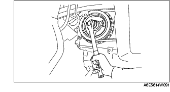
1. Hold the crankshaft pulley to prevent drive plate from rotating.
2. Remove the torque converter nuts from the starter installation hole.
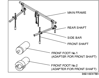
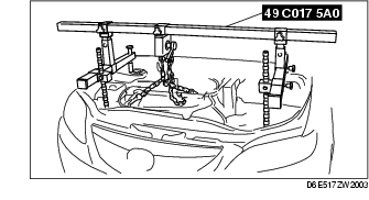
1. Install the SST using the following procedure.

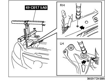
2. Support the engine using the SST.
3. Remove the No.4 engine mount.
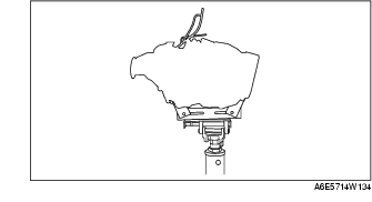
1. Lean the engine toward the transaxle.
2. Support the transaxle on a jack.
3. Remove the transaxle mounting bolts.
4. Remove the transaxle.
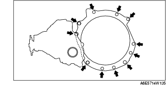
1. Set the transaxle on a jack and lift it.
2. Install the transaxle mounting bolts.
Tightening torque
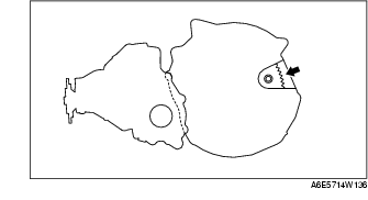
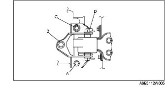
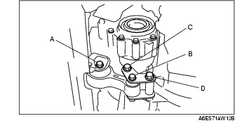
1. Verify that the No.4 engine mount bracket are installed as shown.
2. Lightly tighten the bolt D.
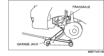
3. Set the transaxle on a garage jack and lift it.
4. Align the hole of the No.4 engine mount bracket with the stud bolts of transaxle.
5. Lightly tighten the bolt A and the nut B, C.
6. Tighten the nut B, C in order of B→ C, then bolt A.
7. Tighten the bolt D.
Tightening torque
1. Hold the crankshaft pulley to prevent drive plate from rotating.
2. Tighten the torque converter mounting nuts.
Tightening torque
1. Loosen the bolt A.
2. Align the hole of the No.1 engine mount rubber with the bracket of transaxle.
3. Lightly tighten the bolt B, then tighten the bolt B.
4. Tighten the bolt A.
Tightening torque
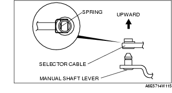
1. Install the selector lever to the manual shaft lever in such a way that the selector cable does not bear a load.
2. Confirm that the end of the manual shaft lever sticks out of the end of the selector cable.