|
1
|
VERIFY AIRFLOW CONDITION
• Switch the ignition ON (engine off or on).
• Set the airflow volume control dial to 1 or more.
• Does air flow from the vent after operating the blower motor?
|
Yes
|
Go to the next step.
|
|
No
|
Go to Step 1 of the following troubleshooting.
|
|
2
|
INSPECT A/C COMPRESSOR OPERATION
• Start engine.
• Turn A/C switch on.
• Does A/C compressor operate?
|
Yes
|
Go to Step 1 of the following troubleshooting.
|
|
No
|
Go to the next step.
|
|
3
|
VERIFY DTCs FOR RELATED MODULES
• Verify DTCs using the M-MDS.
-
― Dash-electrical supply unit
― Body control module (BCM)
• Are any DTCs displayed?
|
Yes
|
Go to the applicable DTC inspection.
― Dash-electrical supply unit
― Body control module (BCM)
|
|
No
|
Go to the next step.
|
|
4
|
VERIFY MAGNETIC CLUTCH OPERATION
• Access PCM PID A/C_SW using the M-MDS.
• Start engine.
• Turn the PID A/C_SW to ON from OFF using the M-MDS simulation function.
• Is the magnetic clutch engaged/disengaged according to the simulation function operation?
|
Yes
|
Go to the next step.
|
|
No
|
Go to Step 9.
|
|
5
|
VERIFY MEASURED VALUE OF A/C PRESSURE SENSOR
• Access PCM PIDs AC_PRES_AFT_COMP and AC_PRES_BEF_EXP_VLV using the M-MDS.
• Monitor the AC_PRES_AFT_COMP and AC_PRES_BEF_EXP_VLV while turning on and off the air conditioner by switching the control panel.
• Are PIDs normal?
|
Yes
|
Go to Step 7.
|
|
No
|
Go to the next step.
|
|
6
|
INSPECT REFRIGERANT PRESSURE SENSOR
• Inspect the refrigerant pressure sensor.
• Is the refrigerant pressure sensor normal?
|
Yes
|
Inspect the following and repair or replace if necessary.
• Refrigerant charge amount (if refrigerant has discharged completely, replace receiver/drier( *1))
Perform the repair completion verification.
|
|
No
|
Replace refrigerant pressure sensor, then perform the repair completion verification.
|
|
7
|
VERIFY MEASURED VALUE OF EVAPORATOR TEMPERATURE SENSOR
• Access dash-electrical supply unit PID EVA_TMP using the M-MDS.
• Turn the climate control unit A/C switch on and off while the PID EVA_TMP is displayed.
• Is the PID normal?
|
Yes
|
Perform the repair completion verification.
|
|
No
|
Go to the next step.
|
|
8
|
INSPECT EVAPORATOR TEMPERATURE SENSOR
• Inspect the evaporator temperature sensor.
• Is the evaporator temperature sensor normal?
|
Yes
|
Refer to the wiring diagram and verify whether or not there is a common connector between evaporator temperature sensor terminal and climate control unit terminal.
If there is a common connector:
• Determine the malfunctioning part by inspecting the common connector and the terminal for corrosion, damage, or pin disconnection.
• Repair or replace the malfunctioning part.
If there is no common connector:
• Repair or replace the wiring harness.
Perform the repair completion verification.
|
|
No
|
Replace the evaporator temperature sensor, then perform the repair completion verification.
|
|
9
|
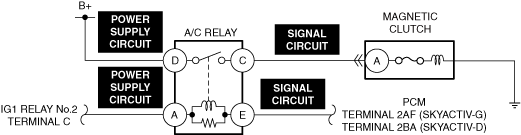
DETERMINE IF MALFUNCTION IS CAUSED BY A/C RELAY CIRCUIT MALFUNCTION OR PCM MALFUNCTION
• Short circuit between A/C relay terminal E (A/C control signal) and ground.
• Is there cool airflow?
|
Yes
|
Repair the short circuit and go to the next step.
|
|
No
|
Go to Step 13.
|
|
10*
|
INSPECT A/C RELAY CONTROL CIRCUIT FOR OPEN CIRCUIT
• Inspect the applicable circuit for open circuit.
• Is the circuit normal?
|
Yes
|
Go to the next step.
|
|
No
|
Repair or replace the malfunctioning location and perform the repair completion verification.
|
|
11
|
INSPECT A/C RELAY CONTROL CIRCUIT FOR SHORT TO GROUND
• Inspect the applicable circuit for a short to ground.
• Is the circuit normal?
|
Yes
|
Go to the next step.
|
|
No
|
Repair or replace the malfunctioning location and perform the repair completion verification.
|
|
12
|
INSPECT MAGNETIC CLUTCH
• Inspect the magnetic clutch.
• Is the magnetic clutch normal?
|
Yes
|
Go to the next step.
|
|
No
|
Replace the magnetic clutch, then perform the repair completion verification.
|
|
13*
|
INSPECT MAGNETIC CLUTCH POWER SUPPLY CIRCUIT FOR SHORT TO GROUND AND OPEN CIRCUIT
• Inspect the power supply circuit for an open circuit and short to ground.
• Is the circuit normal?
|
Yes
|
Go to the next step.
|
|
No
|
Repair or replace the malfunctioning location and perform the repair completion verification.
|
|
14*
|
INSPECT A/C RELAY POWER SUPPLY CIRCUIT FOR OPEN CIRCUIT
• Inspect the power supply circuit for an open circuit.
• Is the circuit normal?
|
Yes
|
Go to the next step.
|
|
No
|
Repair or replace the malfunctioning location and perform the repair completion verification.
|
|
15*
|
INSPECT A/C RELAY POWER SUPPLY CIRCUIT FOR SHORT TO GROUND
• Inspect the applicable circuit for a short to ground.
• Is the circuit normal?
|
Yes
|
Go to the next step.
|
|
No
|
Repair or replace the malfunctioning location and perform the repair completion verification.
|
|
16*
|
INSPECT MAGNETIC CLUTCH CONTROL CIRCUIT FOR OPEN CIRCUIT
• Inspect the applicable circuit for open circuit.
• Is the circuit normal?
|
Yes
|
Go to the next step.
|
|
No
|
Repair or replace the malfunctioning location and perform the repair completion verification.
|
|
17*
|
INSPECT MAGNETIC CLUTCH CONTROL CIRCUIT FOR SHORT TO GROUND
• Inspect the applicable circuit for a short to ground.
• Is the circuit normal?
|
Yes
|
Replace the A/C relay and perform the repair completion verification.
|
|
No
|
Repair or replace the malfunctioning location and perform the repair completion verification.
|
|
Repair completion verification
|
VERIFY THAT MALFUNCTION SYMPTOM DOES NOT RECUR AFTER REPAIR
• Does cool air discharge from the vents? (Are the results of refrigerant system performance test normal?)
|
Yes
|
Troubleshooting completed. Explain repairs to customer.
|
|
No
|
Refer to the controller area network (CAN) malfunction diagnosis flow to inspect for a CAN communication error.
If the CAN communication is normal, perform the diagnosis from Step 1.
|