|
1
|
INSPECT VEHICLE CONTROL MODULE (VCM) AND BODY CONTROL MODULE (BCM) FOR MALFUNCTION
• Switch the ignition OFF, and then switch it ON (engine off).
• Perform the DTC inspection for the vehicle control module (VCM) and the body control module (BCM).
• Is a DTC related to an internal malfunction displayed?
|
Yes
|
Repair the malfunctioning location according to the applicable DTC troubleshooting.
|
|
No
|
Go to the next step.
|
|
2
|
INSPECT DRIVER MONITORING CAMERA UNIT FOR MALFUNCTION
• Perform the DTC inspection for the driver monitoring camera unit.
• Is a DTC displayed?
|
Yes
|
Repair the malfunctioning location according to the applicable DTC troubleshooting.
|
|
No
|
Go to the next step.
|
|
3
|
VERIFY DTCs
• Perform the DTC inspection for the following modules.
-
― PCM
― Mazda M Hybrid battery
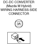
― DC-DC converter (Mazda M Hybrid)
― Integrated starter generator (ISG)
• Are any DTCs displayed?
|
Yes
|
Repair the malfunctioning location according to the applicable DTC troubleshooting.
|
|
No
|
Go to the next step.
|
|
4
|
INSPECT BATTERY FOR MALFUNCTION
• Inspect the applicable part.
• Is the part normal?
|
Yes
|
Go to the next step.
|
|
No
|
Repair or replace the malfunctioning location and perform the repair completion verification.
|
|
5
|
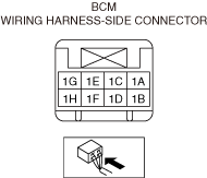
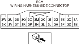
INSPECT VEHICLE CONTROL MODULE (VCM) CONNECTOR FOR MALFUNCTION
• Inspect the applicable connector and terminal.
• Are the connector and terminal normal?
|
Yes
|
Go to the next step.
|
|
No
|
Repair or replace the malfunctioning location and perform the repair completion verification.
|
|
6
|
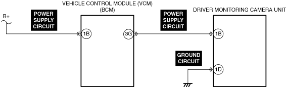
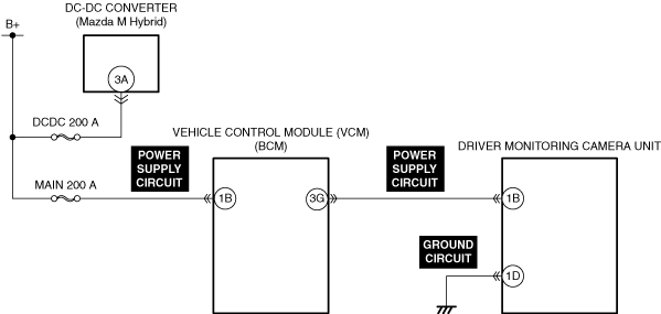
INSPECT VEHICLE CONTROL MODULE (VCM) POWER SUPPLY CIRCUIT FOR SHORT TO GROUND AND OPEN CIRCUIT
• Inspect the power supply circuit for a short to ground and open circuit.
• Is the circuit normal?
|
Yes
|
-
Note
-
• If the diagnostic procedure in Step 7 through Step 15 has been completed, go to Step 16.
Go to the next step.
|
|
No
|
Repair or replace the malfunctioning location and perform the repair completion verification.
|
|
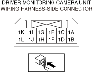
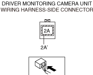
7
|
INSPECT DRIVER MONITORING CAMERA UNIT CONNECTOR FOR MALFUNCTION
• Inspect the applicable connector and terminal.
• Are the connector and terminal normal?
|
Yes
|
Go to the next step.
|
|
No
|
Repair or replace the malfunctioning location and perform the repair completion verification.
|
|
8
|
INSPECT VEHICLE CONTROL MODULE (VCM) CONNECTOR FOR MALFUNCTION
• Inspect the applicable connector and terminal.
• Are the connector and terminal normal?
|
Yes
|
Go to the next step.
|
|
No
|
Repair or replace the malfunctioning location and perform the repair completion verification.
|
|
9
|
INSPECT DRIVER MONITORING CAMERA UNIT GROUND CIRCUIT FOR OPEN CIRCUIT
• Inspect the applicable circuit for an open circuit.
• Is the circuit normal?
|
Yes
|
Go to the next step.
|
|
No
|
Repair or replace the malfunctioning location and perform the repair completion verification.
|
|
10
|
INSPECT DRIVER MONITORING CAMERA UNIT POWER SUPPLY CIRCUIT FOR SHORT TO GROUND AND OPEN CIRCUIT
• Inspect the applicable circuit for a short to ground and an open circuit.
• Is the circuit normal?
|
Yes
|
Go to the next step.
|
|
No
|
Repair or replace the malfunctioning location and perform the repair completion verification.
|
|
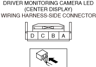
11
|
INSPECT DRIVER MONITORING CAMERA LED CONNECTOR FOR MALFUNCTION
• Inspect the applicable connector and terminal.
• Are the connector and terminal normal?
|
Yes
|
Go to the next step.
|
|
No
|
Repair or replace the malfunctioning location and perform the repair completion verification.
|
|
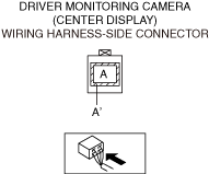
12
|
INSPECT DRIVER MONITORING CAMERA CONNECTOR FOR MALFUNCTION
• Inspect the applicable connector and terminal.
• Are the connector and terminal normal?
|
Yes
|
Go to the next step.
|
|
No
|
Repair or replace the malfunctioning location and perform the repair completion verification.
|
|
13
|
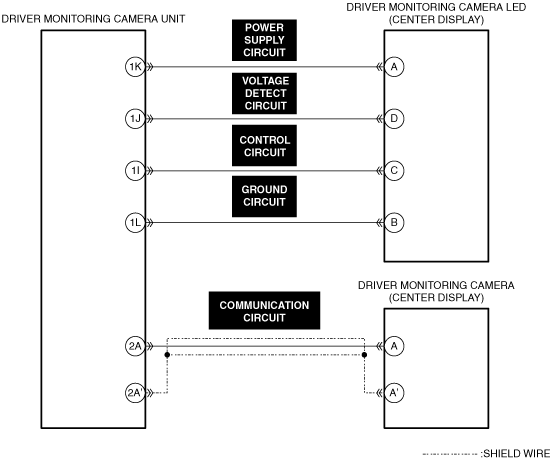
INSPECT DRIVER MONITORING CAMERA COMMUNICATION CIRCUIT FOR SHORT TO GROUND AND OPEN CIRCUIT
• Inspect the applicable circuit for a short to ground and an open circuit.
• Is the circuit normal?
|
Yes
|
Go to the next step.
|
|
No
|
Repair or replace the malfunctioning location and perform the repair completion verification.
|
|
14
|
INSPECT DRIVER MONITORING CAMERA LED POWER SUPPLY CIRCUIT FOR SHORT TO GROUND AND OPEN CIRCUIT
• Inspect the applicable circuit for a short to ground and an open circuit.
• Is the circuit normal?
|
Yes
|
Go to the next step.
|
|
No
|
Repair or replace the malfunctioning location and perform the repair completion verification.
|
|
15
|
INSPECT VEHICLE CONTROL MODULE (VCM) POWER SUPPLY VOLTAGE
• Reconnect all the disconnected connectors.
• Connect the negative battery terminal.
• Measure the voltage at body control module (BCM) terminal 3G.
|
Yes
|
-
Note
-
• If the diagnostic procedure in Step 4 through Step 6 has not been completed, go to Step 4.
Go to the next step.
|
|
No
|
Replace the body control module (BCM) and perform the repair completion verification.
|
|
16
|
INSPECT DRIVER MONITORING CAMERA UNIT FOR MALFUNCTION DEPENDING ON REPEATABILITY
• Install/connect the part removed/disconnected during the troubleshooting procedure.
• Clear the DTC recorded in the memory.
• Perform the DTC inspection for the vehicle control module (VCM).
• Is the same Pending DTC present?
|
Yes
|
Refer to the controller area network (CAN) malfunction diagnosis flow to inspect for a CAN communication error.
If the CAN communication is normal, replace the driver monitoring camera unit and perform the repair completion verification.
|
|
No
|
Go to repair completion verification 2.
|
|
17
|
INSPECT DRIVER MONITORING CAMERA FOR MALFUNCTION DEPENDING ON REPEATABILITY
• Install/connect the part removed/disconnected during the troubleshooting procedure.
• Clear the DTC recorded in the memory.
• Perform the DTC inspection for the vehicle control module (VCM).
• Is the same Pending DTC present?
|
Yes
|
Refer to the controller area network (CAN) malfunction diagnosis flow to inspect for a CAN communication error.
If the CAN communication is normal, replace the center display and perform the repair completion verification.
|
|
No
|
Perform the [Action for Non-repeatable Malfunction].
If DTC is displayed
• Repeat the diagnosis from Step 1.
If DTC is not displayed
• Go to repair completion verification 2.
|
|
Repair completion verification 1
|
VERIFY THAT VEHICLE IS REPAIRED
• Install/connect the part removed/disconnected during the troubleshooting procedure.
• Clear the DTC recorded in the memory.
• Perform the DTC inspection for the vehicle control module (VCM).
• Is the same Pending DTC present?
|
Yes
|
Refer to the controller area network (CAN) malfunction diagnosis flow to inspect for a CAN communication error.
If the CAN communication is normal, perform the diagnosis from Step 1.
• If the malfunction recurs, replace the body control module (BCM), then go to the next step.
|
|
No
|
Go to the next step.
|
|
Repair completion verification 2
|
VERIFY IF OTHER DTCs ARE DISPLAYED
• Perform the DTC inspection.
• Is a DTC displayed?
|
Yes
|
Repair the malfunctioning location according to the applicable DTC troubleshooting.
|
|
No
|
DTC troubleshooting completed.
|