am3zzw00033560
|
DTC P0301:00, P0302:00, P0303:00 OR P0304:00 [PCM (SKYACTIV-X)]
id0102u9500100
Details On DTCs
|
Description |
P0301:00: Cylinder No.1 misfire detected P0302:00: Cylinder No.2 misfire detected P0303:00: Cylinder No.3 misfire detected P0304:00: Cylinder No.4 misfire detected |
|
|---|---|---|
|
Detection condition
|
Determination conditions
|
• Any one of the following conditions is met:
|
|
Preconditions
|
• Battery voltage: 9—18 V*1
• Engine speed: 500—4,500 rpm*1
• Engine coolant temperature: −10 °C {14 °F} or more or 21 °C {70 °F} or more*1 (standard differs depending on engine coolant temperature at engine start)
• Fuel-cut control not implemented
• Crankshaft installation tolerance learning completed
• Engine condition is stabilized (not directly after gear change)
*1: Standard can be verified by displaying PIDs using M-MDS
|
|
|
Malfunction determination period
|
• 200 rotations of crankshaft (misfire which may damage catalytic converter)
• 1,000 rotations of crankshaft (misfire going against emission regulations)
|
|
|
Drive cycle
|
• 2
|
|
|
Self test type
|
• CMDTC self test
|
|
|
Sensor used
|
• CKP sensor
• MAF sensor
• MAP sensor
|
|
|
Fail-safe function
|
• Limits intake air amount.
• Performs fuel-cut control. (If the catalytic converter may be damaged, perform fuel-cut on the cylinder misfiring the most)
• Inhibits the SPCCI control with a large amount of intake air introduced (lean A/F).
• Inhibits the EGR control. (Only when misfiring, which may damage the catalytic converter, is determined)
|
|
|
Vehicle status when DTCs are output
|
• Misfiring which may damage catalytic converter (number of drive cycles: 1):
• Drive cycle directly after above drive cycle (number of drive cycles: 2):
• Rough idling, poor acceleration, stalling
|
|
|
Possible cause
|
• Improper operation of ignition system
• Fuel injector malfunction
• Erratic signal to PCM
• Poor drive belt assembly or adhesion of oil
• Decoupling ring tensioner malfunction
• Air leakage from intake air system (between intake manifold and cylinder head)
• Engine malfunction
• PCM malfunction
|
|
System Wiring Diagram
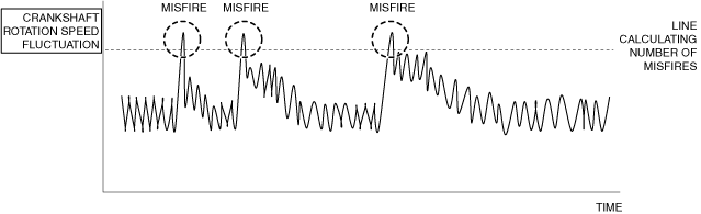
Function Explanation (DTC Detection Outline)
am3zzw00033560
|
Repeatability Verification Procedure
PID Item/Simulation Item Used In Diagnosis
PID/DATA monitor item table
|
PIDs |
Reference |
|---|---|
|
APP1
|
|
|
APP2
|
|
|
ECT
|
|
|
ECT_VOLT
|
|
|
IAT
|
|
|
MAF
|
|
|
MAP
|
|
|
MAP_VOLT
|
|
|
MISFIRE_CYL1_CAT
|
|
|
MISFIRE_CYL2_CAT
|
|
|
MISFIRE_CYL3_CAT
|
|
|
MISFIRE_CYL4_CAT
|
|
|
MISFIRE_CYL1_EMI
|
|
|
MISFIRE_CYL2_EMI
|
|
|
MISFIRE_CYL3_EMI
|
|
|
MISFIRE_CYL4_EMI
|
|
|
ENG_RPM
|
|
|
TP_RELAT
|
|
|
VSS
|
Function Inspection Using M-MDS
|
Step |
Inspection |
Results |
Action |
|---|---|---|---|
|
1
|
PURPOSE: VERIFY RELATED REPAIR INFORMATION OR SERVICE INFORMATION AVAILABILITY
• Verify related Service Bulletins, on-line repair information, or Service Information availability.
• Is any related Information available?
|
Yes
|
Perform repair or diagnosis according to the available information.
• If the vehicle is not repaired, go to the next step.
|
|
No
|
Go to the next step.
|
||
|
2
|
PURPOSE: IDENTIFY TRIGGER DTC FOR FREEZE FRAME DATA
• Is the DTC P0301:00, P0302:00, P0303:00 or P0304:00 on freeze frame data?
|
Yes
|
Go to the next step.
|
|
No
|
Go to the troubleshooting procedure for DTC on freeze frame data.
(See DTC TABLE [PCM (SKYACTIV-X)].)
|
||
|
3
|
PURPOSE: RECORD VEHICLE STATUS WHEN DTC WAS DETECTED TO UTILIZE WITH REPEATABILITY VERIFICATION
• Record the freeze frame data/snapshot data.
|
—
|
Go to the next step.
|
|
4
|
PURPOSE: INSPECT FOR OTHER RELATED DTCs
• Perform the DTC inspection for the PCM.
(See DTC INSPECTION.)
• Are any other DTCs displayed?
|
Yes
|
Repair the malfunctioning location according to the applicable DTC troubleshooting.
(See DTC TABLE [PCM (SKYACTIV-X)].)
|
|
No
|
Go to the next step.
|
||
|
5
|
PURPOSE: VERIFY IF THERE IS PID ITEM CAUSING DRASTIC CHANGES OF ACCELERATION FLUCTUATION BY INPUT SIGNAL TO PCM
• Start the engine.
• Access the following PIDs using the M-MDS:
(See PID/DATA MONITOR INSPECTION.)
• Is there a PID item affected by acceleration fluctuation?
|
Yes
|
Inspect the suspected sensor and related wiring harness.
• If there is any malfunction:
• If there is no malfunction:
|
|
No
|
Go to the next step.
|
||
|
6
|
PURPOSE: RECORD NUMBER OF CURRENT MISFIRES FOR USE WITH MISFIRE INSPECTION
• Display the misfire rate and record the number of misfires.
|
—
|
Go to the next step.
|
|
7
|
PURPOSE: VERIFY IF MISFIRE CAUSE IS BAD SPARK PLUGS
• Switch the spark plugs on a cylinder that is misfiring and a cylinder that is not misfiring.
• Start the engine.
• Verify all accessory loads (A/C, headlights, blower fan, rear window defogger) are off.
• Under no-load conditions (P or N position (ATX)/neutral (MTX)), increase the engine speed to 3,000 rpm.
• Display the misfire rate and record the number of misfires.
• Is there a change from the recorded number of misfires?
|
Yes
|
Go to Troubleshooting Diagnostic Procedure to perform the procedure from Step 1.
|
|
No
|
Go to the next step.
|
||
|
8
|
PURPOSE: VERIFY IF MISFIRE CAUSE IS BAD IGNITION COIL
• Switch the ignition coils on a cylinder that is misfiring and a cylinder that is not misfiring.
• Start the engine.
• Verify all accessory loads (A/C, headlights, blower fan, rear window defogger) are off.
• Under no-load conditions (P or N position (ATX)/neutral (MTX)), increase the engine speed to 3,000 rpm.
• Display the misfire rate and record the number of misfires.
• Is there a change from the recorded number of misfires?
|
Yes
|
Go to Troubleshooting Diagnostic Procedure to perform the procedure from Step 2.
|
|
No
|
Go to Troubleshooting Diagnostic Procedure to perform the procedure from Step 3.
|
Troubleshooting Diagnostic Procedure
|
Step |
Inspection |
Results |
Action |
|---|---|---|---|
|
1
|
PURPOSE: INSPECT SPARK PLUG FOR MALFUNCTION
• Inspect the applicable part.
• Is the part normal?
|
Yes
|
Go to the next step.
|
|
No
|
Repair or replace the malfunctioning location and perform the repair completion verification.
|
||
|
2
|
PURPOSE: INSPECT IGNITION COIL FOR MALFUNCTION
• Inspect the applicable part.
• Is the part normal?
|
Yes
|
Go to the next step.
|
|
No
|
Repair or replace the malfunctioning location and perform the repair completion verification.
|
||
|
3
|
PURPOSE: INSPECT FUEL INJECTOR FOR MALFUNCTION
• Inspect the applicable part.
• Is the part normal?
|
Yes
|
Go to the next step.
|
|
No
|
Repair or replace the malfunctioning location and perform the repair completion verification.
|
||
|
4
|
PURPOSE: VERIFY IF MALFUNCTION RELATED TO INTAKE-AIR SYSTEM IS CAUSE OF MISFIRE
• Visually inspect for loose, cracked or damaged hoses on intake air system.
• Is there any malfunction?
|
Yes
|
Repair or replace the malfunctioning location and perform the repair completion verification.
|
|
No
|
Go to the next step.
|
||
|
5
|
PURPOSE: VERIFY IF POOR DRIVE BELT ASSEMBLY IS CAUSE OF MISFIRE
• Verify the condition of the drive belt assembly.
• Is there any malfunction?
|
Yes
|
Assemble drive belt correctly and perform the repair completion verification.
|
|
No
|
Go to the next step.
|
||
|
6
|
PURPOSE: VERIFY IF FOREIGN MATTER ON DRIVE BELT IS CAUSE OF MISFIRE
• Verify if oil is on the drive belt.
• Is there foreign matter on the drive belt?
|
Yes
|
Remove the foreign matter on the drive belt and perform the repair completion verification.
|
|
No
|
Go to the next step.
|
||
|
7
|
PURPOSE: INSPECT DECOUPLING RING TENSIONER FOR MALFUNCTION
• Inspect the applicable part.
• Is the part normal?
|
Yes
|
Go to the next step.
|
|
No
|
Repair or replace the malfunctioning location and perform the repair completion verification.
|
||
|
8
|
PURPOSE: VERIFY IF MALFUNCTION RELATED TO ENGINE COMPRESSION IS CAUSE OF MISFIRE
• Inspect the engine compression.
• Are compression pressures within specification?
|
Yes
|
Go to the next step.
|
|
No
|
Replace or overhaul the engine and perform the repair completion verification.
|
||
|
9
|
PURPOSE: VERIFY IF MALFUNCTION RELATED TO SEALING OF ENGINE UNIT (COMBUSTION CHAMBER AND ENGINE COOLANT PASSAGE) IS CAUSE OF MISFIRE
• Perform the “ENGINE COOLANT LEAKAGE INSPECTION”.
• Does the radiator cap tester needle drop even though there is no engine coolant leakage from the radiator or the hoses?
|
Yes
|
Engine coolant leakage from the engine (between the combustion chamber and the engine coolant passage) may have occurred.
• Verify the conditions of the gasket and the cylinder head.
|
|
No
|
Go to the next step.
|
||
|
Repair completion verification 1
|
PURPOSE: VERIFY THAT VEHICLE IS REPAIRED
• Install/connect the part removed/disconnected during the troubleshooting procedure.
• Clear the DTC recorded in the memory.
(See CLEARING DTC.)
• Replicate the vehicle conditions at the time the DTC was detected using the following procedure.
• Perform the DTC inspection for the PCM.
(See DTC INSPECTION.)
• Is the same Pending DTC present?
|
Yes
|
Refer to the controller area network (CAN) malfunction diagnosis flow to inspect for a CAN communication error.
If the CAN communication is normal, perform the diagnosis from Step 1.
• If the malfunction recurs, replace the PCM, then go to the next step.
|
|
No
|
Go to the next step.
|
||
|
Repair completion verification 2
|
PURPOSE: VERIFY IF OTHER DTCs DISPLAYED
• Perform the DTC inspection.
(See DTC INSPECTION.)
• Are any other DTCs displayed?
|
Yes
|
Repair the malfunctioning location according to the applicable DTC troubleshooting.
|
|
No
|
DTC troubleshooting completed.
|