Home

Mazdamanuals.com

CLUTCH PIPE AND HOSE REMOVAL/INSTALLATION [C66M-R, C66MX-R]

CLUTCH PIPE AND HOSE REMOVAL/INSTALLATION [C66M-R, C66MX-R]


 id0510mc157000

Caution
•  Do not allow clutch fluid to get on a painted surface. Clutch fluid contains properties which can dissolve the paint. If clutch fluid gets on a painted surface, rinse with water immediately, then wipe the area dry.

1.  Disconnect the negative battery terminal. (See NEGATIVE BATTERY TERMINAL DISCONNECTION/CONNECTION [(E)].)

2.  For SKYACTIV-G 2.0 vehicle, perform the following procedure.

(1)  Remove the plug hole plate. (R.H.D.) (See PLUG HOLE PLATE REMOVAL/INSTALLATION [SKYACTIV-G (WITH CYLINDER DEACTIVATION (E))].) (See PLUG HOLE PLATE REMOVAL/INSTALLATION [SKYACTIV-G (WITHOUT CYLINDER DEACTIVATION (E))].)
(2)  Remove the following parts as a single unit. (See INTAKE-AIR SYSTEM REMOVAL/INSTALLATION [SKYACTIV-G (WITH CYLINDER DEACTIVATION (E))].) (See INTAKE-AIR SYSTEM REMOVAL/INSTALLATION [SKYACTIV-G (WITHOUT CYLINDER DEACTIVATION (E))].)
•  Air cleaner cover
•  Air cleaner element
•  Fresh-air duct
•  Air cleaner case
•  Air hose
•  Resonance chamber
(3)  Remove the battery. (See BATTERY REMOVAL/INSTALLATION [SKYACTIV-G (WITH CYLINDER DEACTIVATION (E))].) (See BATTERY REMOVAL/INSTALLATION [SKYACTIV-G (WITHOUT CYLINDER DEACTIVATION (E))].)
(4)  Remove the battery tray and PCM component as a single unit. (See BATTERY REMOVAL/INSTALLATION [SKYACTIV-G (WITH CYLINDER DEACTIVATION (E))].) (See BATTERY REMOVAL/INSTALLATION [SKYACTIV-G (WITHOUT CYLINDER DEACTIVATION (E))].)

3.  For SKYACTIV-D 1.8 vehicle, perform the following procedure.

(1)  Remove the engine cover. (R.H.D.) (See ENGINE COVER REMOVAL/INSTALLATION [SKYACTIV-D 1.8].)
(2)  Remove the following parts as a single unit. (See INTAKE-AIR SYSTEM REMOVAL/INSTALLATION [SKYACTIV-D 1.8].)
•  Air cleaner cover
•  Air cleaner element
•  Fresh-air duct
•  Air cleaner case
•  Air hose
(3)  Remove the battery and battery tray. (See BATTERY REMOVAL/INSTALLATION [SKYACTIV-D 1.8].)

4.  For SKYACTIV-X 2.0 vehicle, perform the following procedure.

(1)  Remove the engine cover. (R.H.D.) (See ENGINE COVER REMOVAL/INSTALLATION [SKYACTIV-X 2.0].)
(2)  Remove the side wall. (R.H.D.) (See SIDE WALL REMOVAL/INSTALLATION [SKYACTIV-X 2.0].)
(3)  Open the engine cover. (L.H.D.)
(4)  Remove the left wall (front). (L.H.D.) (See SIDE WALL REMOVAL/INSTALLATION [SKYACTIV-X 2.0].)
(5)  Remove the following parts as a single unit. (L.H.D.) (See AIR CLEANER REMOVAL/INSTALLATION [SKYACTIV-X 2.0].)
•  Air cleaner cover
•  Air cleaner element
•  Fresh-air duct
•  Air cleaner case
•  Air hose
(6)  Remove the battery. (See BATTERY REMOVAL/INSTALLATION [SKYACTIV-X 2.0].)
(7)  Remove the battery tray and PCM component as a single unit. (See BATTERY REMOVAL/INSTALLATION [SKYACTIV-X 2.0].)

5.  Remove the insulator. (R.H.D.)

ac30zw00001929

6.  Remove the insulator. (R.H.D.)

ac30zw00001930

7.  Disconnect the vacuum pipe and bracket. (R.H.D.)

ac30zw00001931

8.  Remove the clutch reserve hose while pressing the point indicated by the arrow in the figure. (See Clutch Reserve Hose Installation Note.)

ac30zw00002440

9.  Pull and disengage the clips of the connector area.

ac30zw00000589

10.  Pull out the clutch pipes and hose connector straight to detach it.

11.  Remove the clutch pipes and hose. (See Clutch Pipes And Hose Installation Note.)

Caution
•  Do not scratch the seal surface.
•  Do not let foreign matter enter the clutch reserve hose, clutch pipe and hose, and transaxle. Otherwise, it could cause a malfunction.

12.  Install in the reverse order of removal.

13.  Bleed the air from the clutch system. (See CLUTCH FLUID REPLACEMENT/AIR BLEEDING [C66M-R, C66MX-R].)


Clutch Reserve Hose Installation Note

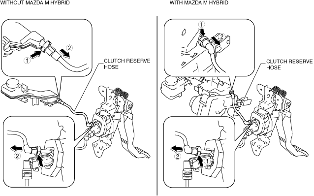
1.  Insert the clutch reserve hose connector straight.

Note
•  When the connector is engaged, a click sound is heard.

2.  Pull each engagement of the clutch reserve hose and clutch pipes and hose, verify that they are engaged, and then press all of them again.


Clutch Pipes And Hose Installation Note

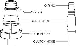
1.  Verify that the O-ring is installed to the clutch pipes and hose connector.

am3zzw00021722

Caution
•  The O-rings installed to the ends of the clutch pipe and hose connectors may fall off or remain on the receiver side when the clutch pipe and hose are disconnected. If the clutch pipe and hose are assembled without installing O-rings, clutch fluid could leak from the connection areas.

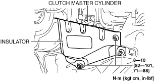
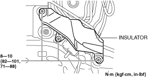
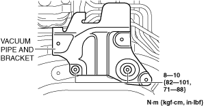
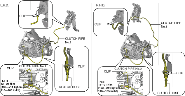
2.  Install the clutch pipes and hose.

(1)  Press in the clips in the connector areas.
(2)  Insert the clutch pipes and hose connector straight.
Note
•  When the connector is engaged, a click sound is heard.
(3)  Install the clutch pipes and hose.