 |
ac30zw00004631
STEERING GEAR AND LINKAGE INSPECTION [(E)]
id0613008020x2
1. Disconnect the negative battery terminal and wait for 1 min or more. (With Mazda M Hybrid) (See NEGATIVE BATTERY TERMINAL DISCONNECTION/CONNECTION [(E)].)
2. Remove the wheel and tire. (See WHEEL AND TIRE REMOVAL/INSTALLATION.)
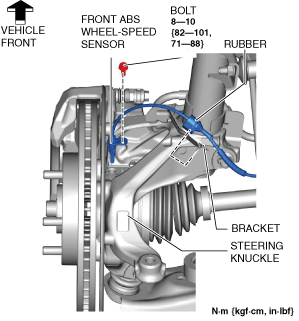
3. Disconnect the rubber from the bracket.
ac30zw00004631
|
4. Disconnect the front ABS wheel-speed sensor wiring harness on the steering knuckle and set it aside so that it does not interfere with the servicing.
5. Remove the tunnel cover. (See EXHAUST SYSTEM REMOVAL/INSTALLATION [SKYACTIV-G (WITHOUT CYLINDER DEACTIVATION (E))].) (See EXHAUST SYSTEM REMOVAL/INSTALLATION [SKYACTIV-G (WITH CYLINDER DEACTIVATION (E))].) (See MIDDLE PIPE REMOVAL/INSTALLATION [SKYACTIV-X 2.0].) (See EXHAUST SYSTEM REMOVAL/INSTALLATION [SKYACTIV-D 1.8].)
6. Remove the following parts.
7. Disconnect the tie-rod end from the steering knuckle. (See TIE-ROD END REPLACEMENT [(E)].)
8. Disconnect the front lower arm ball joint from the steering knuckle. (See FRONT LOWER ARM REMOVAL/INSTALLATION [(E)].)
9. Remove the floor under cover No.1. (With Mazda M Hybrid) (See FLOOR UNDER COVER REMOVAL/INSTALLATION.)
10. Remove the front deflector. (See DEFLECTOR REMOVAL/INSTALLATION.)
11. Remove the front splash shield. (See SPLASH SHIELD REMOVAL/INSTALLATION.)
12. Remove the joint cover. (See INTERMEDIATE SHAFT REMOVAL/INSTALLATION [(E)].)
13. Disconnect the intermediate shaft from the steering gear and linkage. (See INTERMEDIATE SHAFT REMOVAL/INSTALLATION [(E)].)
14. Disconnect the ground plate. (With Mazda M Hybrid) (See GROUND PLATE DISCONNECTION/CONNECTION.)
15. Remove the front crossmember component. (See FRONT CROSSMEMBER REMOVAL/INSTALLATION [(E)].)
16. Remove the hole cover No.1 and hole cover No.2. (See FRONT CROSSMEMBER REMOVAL/INSTALLATION [(E)].)
17. Remove the steering gear and linkage from the front crossmember component. (See STEERING GEAR AND LINKAGE REMOVAL/INSTALLATION [(E)].)
18. Remove the locknuts, tie-rod ends, boot clamps, boot bands, and boots from the steering gear and linkage. (See STEERING GEAR AND LINKAGE DISASSEMBLY [(E)].)
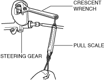
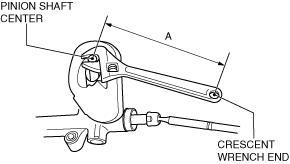
19. Measure the pinion shaft rotation torque using a crescent wrench and pull scale. (Measurement speed reference: 5 rpm)
ac8wzw00001514
|
ac8wzw00001515
|