1. : Mazda SST number
2. : Global SST number
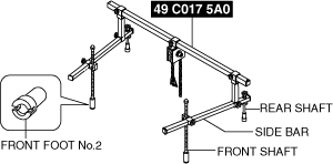
1: 49 C017 5A0
2: –
Engine support set
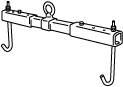
1: 49 UN30 3050
2: 303–050
Engine lifting bracket
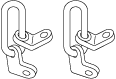
1: 49 L017 5A0
2: –
Support hanger
ENGINE MOUNT DISASSEMBLY/ASSEMBLY [SKYACTIV-X 2.0]
id0110hf806900
Special Service Tool (SST)
|
1. : Mazda SST number
2. : Global SST number
|
|||||
|
1: 49 C017 5A0
2: –
Engine support set
|
|
1: 49 UN30 3050
2: 303–050
Engine lifting bracket
|
|
1: 49 L017 5A0
2: –
Support hanger
|
|
Replacement part
|
Idle pulley
Quantity: 1
Location of use: Engine bracket
|
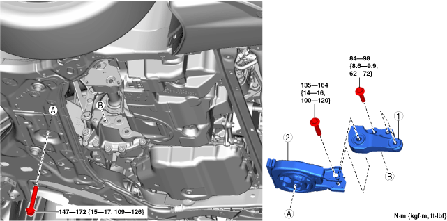
No.1 Engine Mount (2WD)
1. Remove the front under cover No.2. (See FRONT UNDER COVER No.2 REMOVAL/INSTALLATION.)
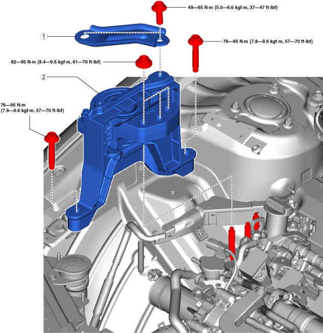
2. Remove in the order indicated in the table.
3. Install in the reverse order of removal.
am3zzw00035947
|
|
1
|
No.1 engine mount bracket
|
|
2
|
No.1 engine mount rubber
|
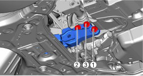
No.1 engine mount installation note (2WD)
1. Tighten the No.1 engine mount bracket installation bolts in the order shown in the figure.
am3zzw00035948
|
2. Temporarily tighten the No.1 engine mount rubber installation bolts in the order shown in the figure.
am3zzw00035949
|
3. Tighten the No.1 engine mount rubber installation bolts in the order shown in the figure.
am3zzw00035949
|
No.1 Engine Mount (AWD)
1. Remove the wheel and tire. (See WHEEL AND TIRE REMOVAL/INSTALLATION.)
2. Remove the front under cover No.2. (See FRONT UNDER COVER No.2 REMOVAL/INSTALLATION.)
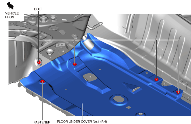
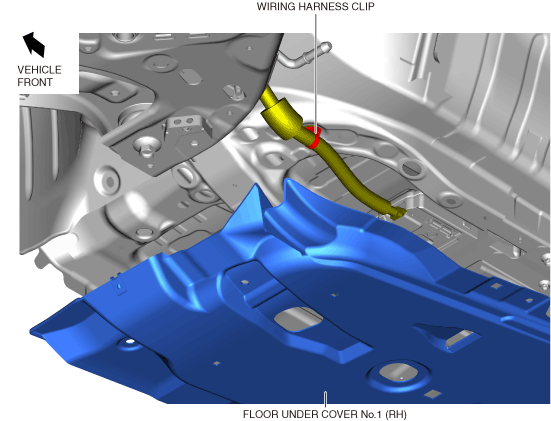
3. Remove the front under cover No.1. (See FRONT UNDER COVER No.1 REMOVAL/INSTALLATION.)
4. When removing the front lower arm (RH), perform the following procedure.
ac30zw00002148
|
ac30zw00002149
|
ac30zw00002150
|
5. Lower the front crossmember approx. 30 mm to the position where the No.1 engine mount bracket can be removed. (See FRONT CROSSMEMBER REMOVAL/INSTALLATION [(E)].)
6. Remove in the order indicated in the table.
7. Install in the reverse order of removal.
am3zzw00035947
|
|
1
|
No.1 engine mount bracket
|
|
2
|
No.1 engine mount rubber
|
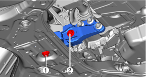
No.1 engine mount installation note (AWD)
1. Tighten the No.1 engine mount bracket installation bolts in the order shown in the figure.
am3zzw00035950
|
2. Tighten the No.1 engine mount rubber installation bolts in the order shown in the figure.
am30jw00000488
|
No.3 Engine Mount
1. Remove the engine cover. (See ENGINE COVER REMOVAL/INSTALLATION [SKYACTIV-X 2.0].)
2. Remove the following parts. (See SIDE WALL REMOVAL/INSTALLATION [SKYACTIV-X 2.0].)
3. Remove the coolant reserve tank. (See COOLANT RESERVE TANK REMOVAL/INSTALLATION [SKYACTIV-X 2.0].)
4. Remove the front under cover No.2. (See FRONT UNDER COVER No.2 REMOVAL/INSTALLATION.)
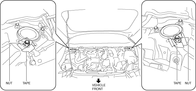
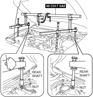
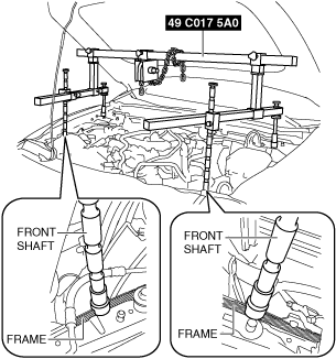
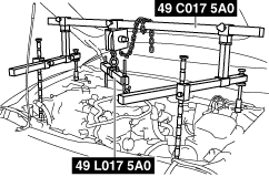
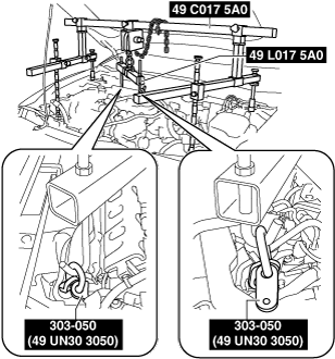
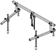
5. Install the SST using the following procedure:
am3uuw00008845
|
am3zzw00035951
|
Engine front side
am3zzw00035952
|
Engine rear side
am3zzw00035953
|
am3zzw00022328
|
am3zzw00022329
|
am3zzw00031878
|
am3zzw00031879
|
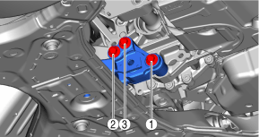
6. Remove in the order indicated in the table.
7. Install in the reverse order of removal.
am3zzw00035606
|
|
1
|
No.3 engine mount bracket
|
|
2
|
No.3 engine mount
|
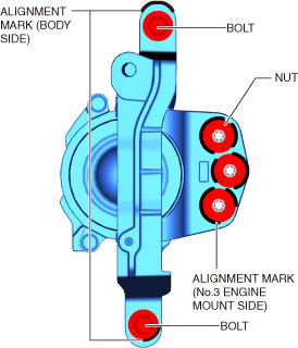
No.3 engine mount removal note
1. Place alignment marks on the locations shown in the figure so that they can be assembled to the same positions as before removal.
am3zzw00035607
|
2. Remove the No.3 engine mount.
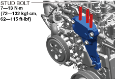
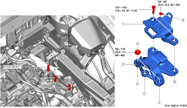
No.3 engine mount installation note
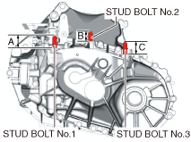
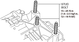
1. Tighten the engine bracket stud bolts.
ac30zw00004662
|
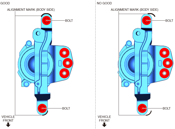
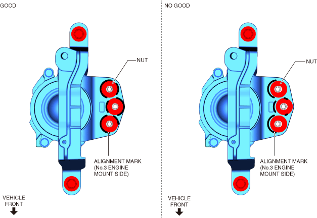
2. Temporarily tighten the No.3 engine mount installation bolts and nuts using the following procedure:
am3zzw00035954
|
am3zzw00035955
|
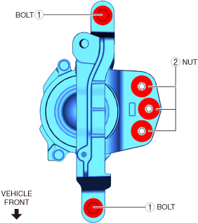
3. Tighten the No.3 engine mount installation bolts and nuts in the order shown in the figure.
am3zzw00035956
|
4. Remove the engine lifter or garage jack.
5. Install in the reverse order of removal.
Engine Bracket
1. Remove the No.3 engine mount.
ac30zw00005136
|
2. Remove the water pump drive belt. (See DRIVE BELT REMOVAL/INSTALLATION [SKYACTIV-X 2.0].)
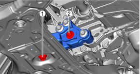
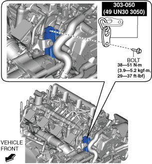
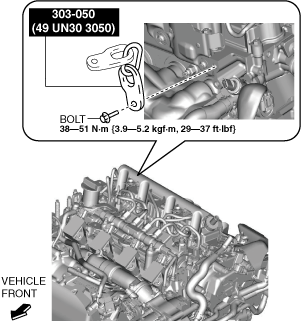
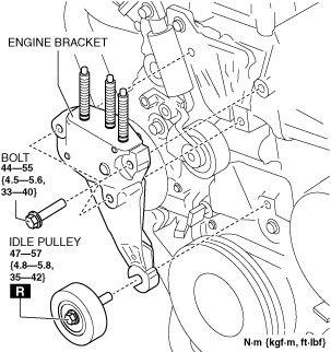
3. Remove the idle pulley and the bolts shown in the figure and remove the engine bracket.
4. Install in the reverse order of removal.
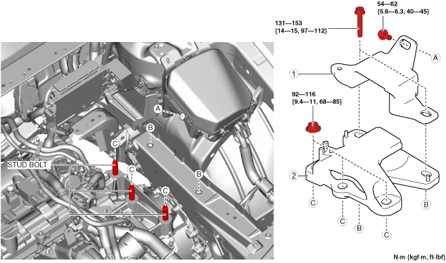
No.4 Engine Mount
1. Disconnect the negative battery terminal. (See NEGATIVE BATTERY TERMINAL DISCONNECTION/CONNECTION [(E)].)
2. Remove the following parts as a single unit.(See AIR CLEANER REMOVAL/INSTALLATION [SKYACTIV-X 2.0].)
3. Remove the battery. (See BATTERY REMOVAL/INSTALLATION [SKYACTIV-X 2.0].)
4. Remove the battery tray and PCM as a single unit. (See BATTERY REMOVAL/INSTALLATION [SKYACTIV-X 2.0].)
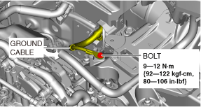
5. Remove the bolt shown in the figure and set the ground cable aside.
am3zzw00035608
|
6. Remove the front under cover No.2. (See FRONT UNDER COVER No.2 REMOVAL/INSTALLATION.)
7. Install the SST using the following procedure:
am3uuw00008845
|
am3zzw00035951
|
Engine front side
am3zzw00035952
|
Engine rear side
am3zzw00035953
|
am3zzw00022328
|
am3zzw00022329
|
am3zzw00031878
|
am3zzw00031879
|
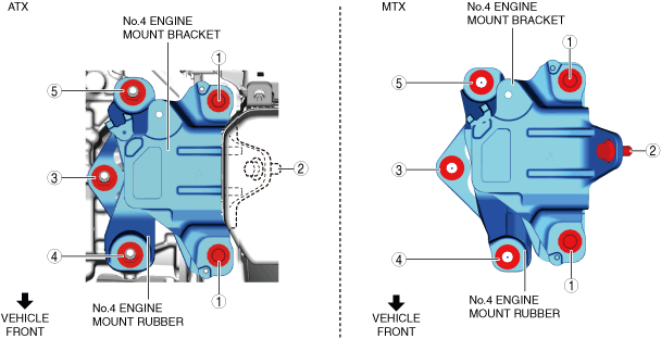
8. Remove in the order indicated in the table.
9. Install in the reverse order of removal.
Except Chinese specs.
am3zzw00035957
|
Chinese specs.
ac30zw00004194
|
|
1
|
No.4 engine mount bracket
|
|
2
|
No.4 engine mount rubber
|
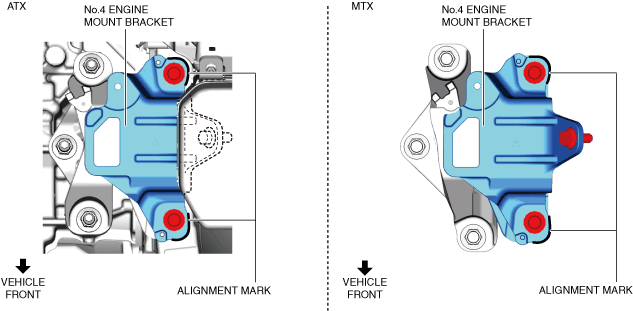
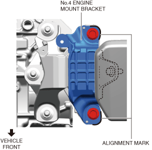
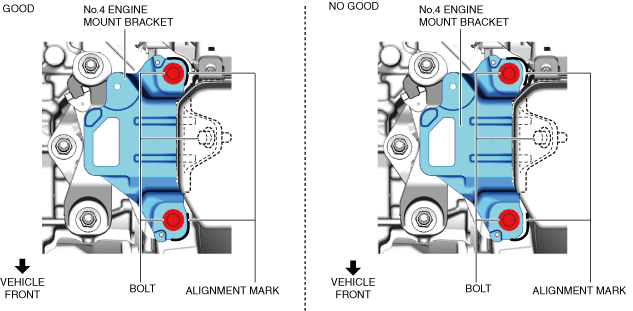
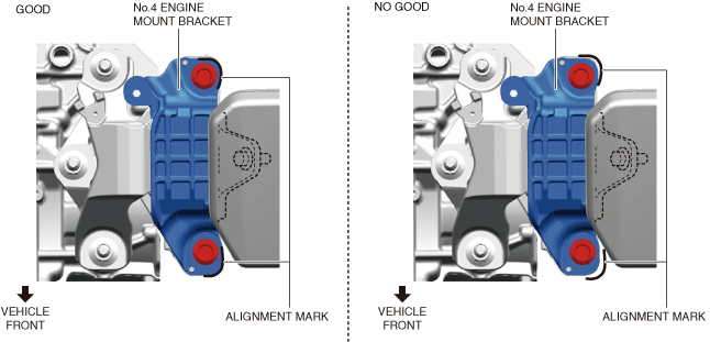
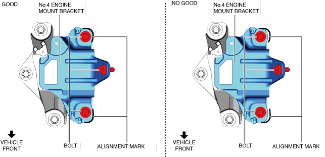
No.4 engine mount bracket removal note
1. Place alignment marks on the locations shown in the figure so that they can be assembled to the same positions as before removal.
Except Chinese specs.
am3zzw00035958
|
Chinese specs.
ac30zw00004195
|
2. Before removing the No.4 engine mount bracket, support the transaxle using a commercially available engine lifter or garage jack.
3. Remove the No.4 engine mount bracket.
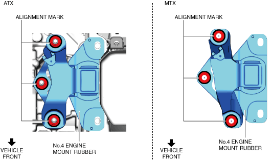
No.4 engine mount rubber removal note
1. Before removing the No.4 engine mount rubber, support the transaxle using a commercially available engine lifter or garage jack.
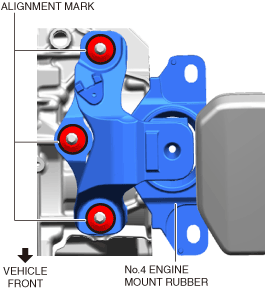
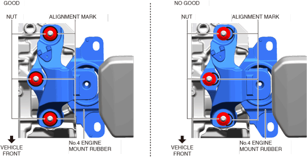
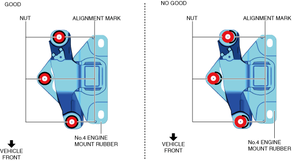
2. Place alignment marks on the locations shown in the figure so that they can be assembled to the same positions as before removal.
Except Chinese specs.
am3zzw00035959
|
Chinese specs.
ac30zw00004196
|
3. Remove the No.4 engine mount rubber.
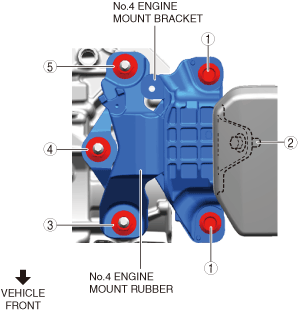
No.4 engine mount bracket and rubber installation note
1. Measure the projection of the transaxle stud bolts. (MTX)
am3zzw00031595
|
2. Tighten the transaxle stud bolts. (ATX)
am3zzw00031596
|
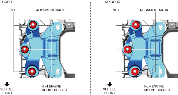
3. Align the alignment marks on the No.4 engine mount rubber and nuts, and temporarily tighten the nuts shown in the figure.
ATX (Except Chinese specs.)
am3zzw00035960
|
ATX (Chinese specs.)
ac30zw00004197
|
MTX
am3zzw00035961
|
4. Align the alignment marks on the No.4 engine mount bracket and bolts, and temporarily tighten the bolts shown in the figure.
ATX (Except Chinese specs.)
am3zzw00035962
|
ATX (Chinese specs.)
ac30zw00004198
|
MTX
am3zzw00035963
|
5. Install the No.4 engine mount bracket and rubber and temporarily tighten the nuts and bolts shown in the figure.
Except Chinese specs.
ac30zw00004856
|
Chinese specs.
ac30zw00004199
|