|
1
|
INSPECT BATTERY VOLTAGE
• Is the battery terminal voltage normal?
|
Yes
|
Make sure that battery terminal connection is okay.
Go to the next step.
|
|
No
|
Charge or replace the battery, then perform the repair completion verification.
|
|
2
|
INSPECT BATTERY GRAVITY
• Is the battery specific gravity as specified?
|
Yes
|
Go to the next step.
|
|
No
|
Replace the battery, then perform the repair completion verification.
|
|
3
|
INSPECT CHARGING SYSTEM
• Are the generator and drive belt tension normal?
|
Yes
|
Go to the next step.
|
|
No
|
Replace the generator and/or drive belt if necessary.
Perform the repair completion verification.
|
|
4
|
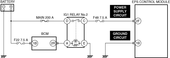
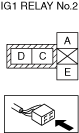
INSPECT IG1 RELAY No.2
• Inspect the IG1 relay No.2.
• Is the relay normal?
|
Yes
|
Go to the next step.
|
|
No
|
Replace the IG1 relay No.2 and perform the repair completion verification.
)
|
|
5
|
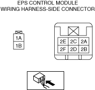
INSPECT EPS CONTROL MODULE POWER SUPPLY CIRCUIT FOR OPEN OR SHORT CIRCUIT
• Inspect the power supply circuit for an open circuit and short to ground.
• Is the circuit normal?
|
Yes
|
Go to the next step.
|
|
No
|
Repair or replace the malfunctioning location and perform the repair completion verification.
|
|
6
|
INSPECT EPS CONTROL MODULE GROUND CIRCUIT FOR POOR GROUND OR OPEN CIRCUIT
• Inspect the applicable circuit for an open circuit.
• Is the circuit normal?
|
Yes
|
Go to the next step.
|
|
No
|
Repair or replace the malfunctioning location and perform the repair completion verification.
|
|
Repair completion verification 1
|
VERIFY DTC TROUBLESHOOTING COMPLETED
• Using the M-MDS, clear the DTC from the EPS control module.
• Using the M-MDS, perform the EPS control module DTC inspection.
• Is the same Pending DTC present?
|
Yes
|
Refer to the controller area network (CAN) malfunction diagnosis flow to inspect for a CAN communication error.
If the CAN communication is normal, perform the diagnosis from Step 1.
• If the malfunction recurs, replace the EPS control module.
Go to the next step.
|
|
No
|
Go to the next step.
|
|
Repair completion verification 2
|
VERIFY NO DTC IS PRESENT
• Are any DTCs present?
|
Yes
|
Go to applicable DTC inspection.
|
|
No
|
DTC troubleshooting completed.
|