CLUTCH PEDAL REMOVAL/INSTALLATION [C66M-R, C66MX-R]
Home
Caution
• Do not allow clutch fluid to get on a painted surface. Clutch fluid contains properties which can dissolve the paint. If clutch fluid gets on a painted surface, rinse with water immediately, then wipe the area dry.
1. Disconnect the negative battery terminal. (See NEGATIVE BATTERY TERMINAL DISCONNECTION/CONNECTION [(E)]
2. For SKYACTIV-G 2.0 vehicle, perform the following procedure.
(1) Remove the plug hole plate. (R.H.D.) (See PLUG HOLE PLATE REMOVAL/INSTALLATION [SKYACTIV-G (WITH CYLINDER DEACTIVATION (E))] PLUG HOLE PLATE REMOVAL/INSTALLATION [SKYACTIV-G (WITHOUT CYLINDER DEACTIVATION (E))]
(2) Remove the following parts as a single unit. (L.H.D.) (See INTAKE-AIR SYSTEM REMOVAL/INSTALLATION [SKYACTIV-G (WITH CYLINDER DEACTIVATION (E))] INTAKE-AIR SYSTEM REMOVAL/INSTALLATION [SKYACTIV-G (WITHOUT CYLINDER DEACTIVATION (E))]
• Air cleaner cover
• Air cleaner element
• Fresh-air duct
• Air cleaner case
• Air hose
• Resonance chamber
(3) Remove the battery. (L.H.D.) (See BATTERY REMOVAL/INSTALLATION [SKYACTIV-G (WITH CYLINDER DEACTIVATION (E))] BATTERY REMOVAL/INSTALLATION [SKYACTIV-G (WITHOUT CYLINDER DEACTIVATION (E))]
(4) Remove the battery tray and PCM component as a single unit. (L.H.D.) (See BATTERY REMOVAL/INSTALLATION [SKYACTIV-G (WITH CYLINDER DEACTIVATION (E))] BATTERY REMOVAL/INSTALLATION [SKYACTIV-G (WITHOUT CYLINDER DEACTIVATION (E))]
3. For SKYACTIV-D 1.8 vehicle, perform the following procedure.
(1) Remove the engine cover. (R.H.D.) (See ENGINE COVER REMOVAL/INSTALLATION [SKYACTIV-D 1.8]
(2) Remove the battery. (L.H.D.) (See BATTERY REMOVAL/INSTALLATION [SKYACTIV-D 1.8]
4. For SKYACTIV-X 2.0 vehicle, perform the following procedure.
(1) Remove the engine cover. (R.H.D.) (See ENGINE COVER REMOVAL/INSTALLATION [SKYACTIV-X 2.0]
(2) Remove the side wall. (R.H.D.) (See SIDE WALL REMOVAL/INSTALLATION [SKYACTIV-X 2.0]
(3) Open the engine cover. (L.H.D.)
(4) Remove the left wall (front). (L.H.D.) (See SIDE WALL REMOVAL/INSTALLATION [SKYACTIV-X 2.0]
(5) Remove the following parts as a single unit. (L.H.D.) (See AIR CLEANER REMOVAL/INSTALLATION [SKYACTIV-X 2.0]
• Air cleaner cover
• Air cleaner element
• Fresh-air duct
• Air cleaner case
• Air hose
(6) Remove the battery. (L.H.D.) (See BATTERY REMOVAL/INSTALLATION [SKYACTIV-X 2.0]
(7) Remove the battery tray and PCM component as a single unit. (L.H.D.) (See BATTERY REMOVAL/INSTALLATION [SKYACTIV-X 2.0]
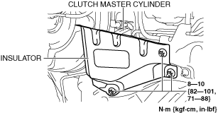
5. Remove the insulator. (R.H.D.)
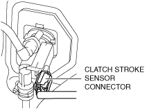
6. Disconnect the clutch stroke sensor connector.
7. Remove the bracket from the steering shaft. (See STEERING WHEEL AND COLUMN REMOVAL/INSTALLATION [(E)]
8. Disconnect the starter interlock switch connector. (See STARTER INTERLOCK SWITCH REMOVAL/INSTALLATION [C66M-R, C66MX-R]
9. Remove the joint cover. (See STEERING WHEEL AND COLUMN REMOVAL/INSTALLATION [(E)]
10. Disconnect the clutch pipe No.1 from clutch master cylinder, and plug it to avoid clutch fluid leakage. (See CLUTCH PIPE AND HOSE REMOVAL/INSTALLATION [C66M-R, C66MX-R]
11. Disconnect the clutch reserve hose from clutch master cylinder, and plug it to avoid clutch fluid leakage. (See CLUTCH PIPE AND HOSE REMOVAL/INSTALLATION [C66M-R, C66MX-R]
12. Remove the nuts.
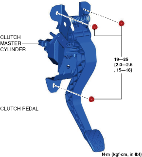
13. Remove the clutch pedal and the clutch master cylinder as a single unit.
14. Remove the starter interlock switch. (See STARTER INTERLOCK SWITCH REMOVAL/INSTALLATION [C66M-R, C66MX-R]
Caution
• When removing the insulator, completely detach the insulator tabs so as not to damage them. If the tabs are not completely detached, they may be damaged when the insulator is removed.
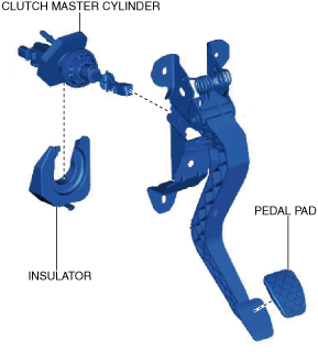
15. Remove the insulator. (See Insulator Installation Note
16. Remove the clutch master cylinder. (See CLUTCH MASTER CYLINDER REMOVAL/INSTALLATION [C66M-R, C66MX-R]
17. Remove the pedal pad.
18. Install in the reverse order of removal.
19. Bleed the air from the clutch system. (See CLUTCH FLUID REPLACEMENT/AIR BLEEDING [C66M-R, C66MX-R]
20. Inspect the clutch pedal. (See CLUTCH PEDAL INSPECTION [C66M-R, C66MX-R]
21. Fully depress the clutch pedal, and verify that the engine starts.
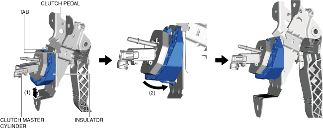
1. Move the insulator in the direction of arrow (1) shown in the figure and hook the insulator tabs onto the clutch pedal.
2. Press the insulator in the direction of arrow (2) shown in the figure and install the insulator.
3. Verify that the insulator is securely installed.