• Performing the following procedures could cause an open circuit in the front ABS wheel-speed sensor wiring harness if it is pulled by mistake. Before servicing, disconnect the front ABS wheel-speed sensor and set it aside so that the wiring harness will not be pulled by mistake.
• Secure the steering wheel using tape or a cable to prevent the steering shaft from rotating after disconnecting the steering shaft. If the steering wheel rotates after the steering shaft and the steering gear and linkage are disconnected, the internal parts of the clock spring could be damaged.
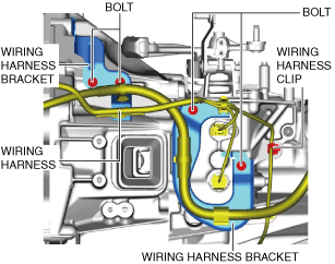
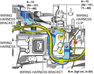
(12) Remove the wiring harness clip and bolts, and set the wiring harnesses and wiring harness brackets in a place which does not interfere with servicing.
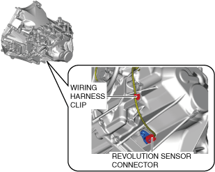
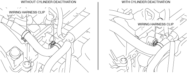
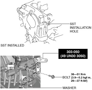
(4) To enable to install the SST, disconnect the clip shown in the figure and set the wiring harness aside.
ac30zw00003778
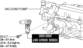
(5) Install the SST using a bolt with part number 99794 1025 or an M10—1.25, length 25 mm {0.98 in} bolt, and a washer as shown in the figure.
Engine front side
ac30zw00000603
Engine rear side
am3zzw00031863
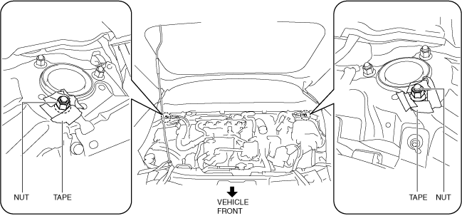
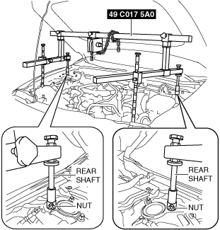
(6) As shown in the figure, set the rear shafts of the SST to the left and right front shock absorber nuts.
am3zzw00022328
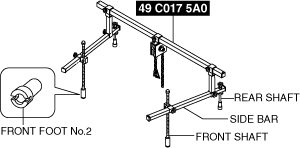
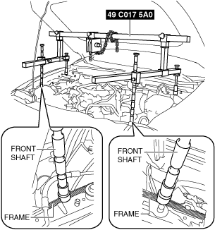
(7) Set the front shafts of the SST (49 C017 5A0) as shown in the figure.
am3zzw00022329
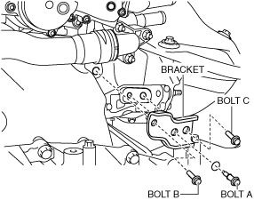
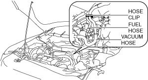
(8) To prevent interference of the SST with the hose when assembling the SST (49 L017 5A0), disconnect the hose clip from the bracket shown in the figure and set the fuel hose and vacuum hose aside.
am3zzw00022330
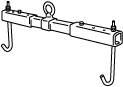
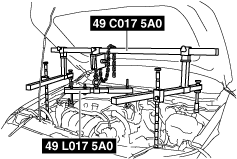
(9) Install the SST (49 L017 5A0) to the SST (49 C017 5A0) as shown in the figure.
am3zzw00022331
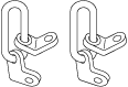
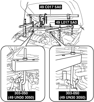
(10) Install the SST (49 L017 5A0) to the SST (49 UN30 3050) with the hook of the SST (49 L017 5A0) facing outward.
am3zzw00022332
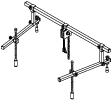
(11) Adjust the height of the left and right side bars so that they are leveled, then tighten each part of the SST.
(12) Apply tension to the chain to support the engine and verify that the engine is securely hung.
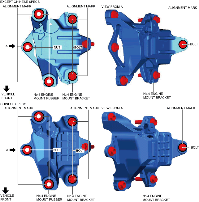
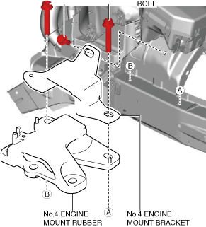
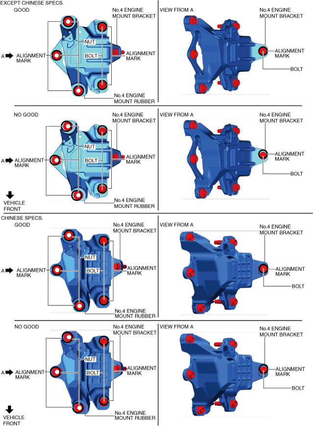
No.4 engine mount rubber and No.4 engine mount bracket removal note
Caution
• Slots have been adopted for the No.4 engine mount rubber and No.4 engine mount bracket installation holes. If the No.4 engine mount rubber and No.4 engine mount bracket deviate from their original positions when they are installed, engine noise or vibration could increase. When installing the No.4 engine mount rubber and No.4 engine mount bracket, align them to the alignment marks placed during removal and install them to their original positions.
1. Place alignment marks on the locations shown in the figure so that they can be assembled to the same positions as before removal.
ac30zw00004133
Note
• Place the alignment marks so that the contour of the nuts and bolts are outlined.
2. Remove the No.4 engine mount rubber and the No.4 engine mount bracket.
Transaxle mounting bolt removal note
Warning
• Remove the manual transaxle carefully, holding it steady. If the manual transaxle falls it could be damaged or cause injury.
1. Adjust the SST and lean the engine toward the manual transaxle.
am3zzw00022331
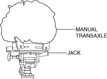
2. Support the manual transaxle on a jack.
ac5uuw00003118
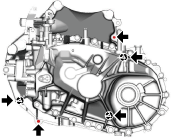
3. Remove the transaxle mounting bolts (lower side).
am3zzw00027658
4. Remove the manual transaxle.
Installation
Warning
• Install the manual transaxle carefully, holding it steady. If the manual transaxle falls it could be damaged or cause injury.
Caution
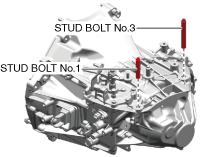
• To prevent the stud bolts from contacting the front side frame, remove stud bolts No.1 and No.3 from the manual transaxle component when replacing the manual transaxle component.
ac30zw00004694
1. Set the manual transaxle on a jack and lift into place.
ac5uuw00003118
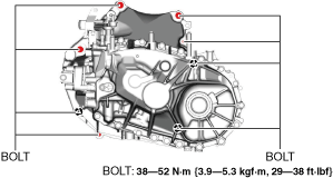
2. Install the manual transaxle to the engine, and tighten the transaxle mounting bolts.
am3zzw00031864
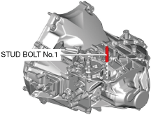
3. Install stud bolt No.1.
am3zzw00021670
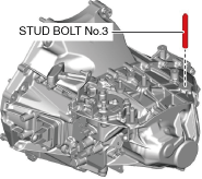
4. Install stud bolt No.3.
am3zzw00021671
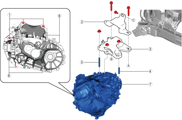
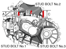
5. Measure the projection of the stud bolts.
am3zzw00021672
Projection A of stud bolt No.1
40.0—42.0 mm {1.58—1.65 in}
Projection B of stud bolt No.2
30.7—32.7 mm {1.21—1.28 in}
Projection C of stud bolt No.3
70.7—72.7 mm {2.79—2.86 in}
Note
• If the projection amount is not within the range, adjust the projection amount of the stud bolts.
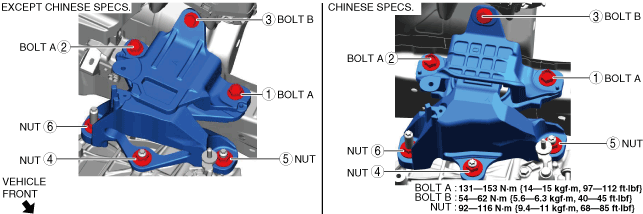
6. Install the No.4 engine mount bracket and the No.4 engine mount rubber, and temporarily tighten the bolts shown in the figure.
ac30zw00004134
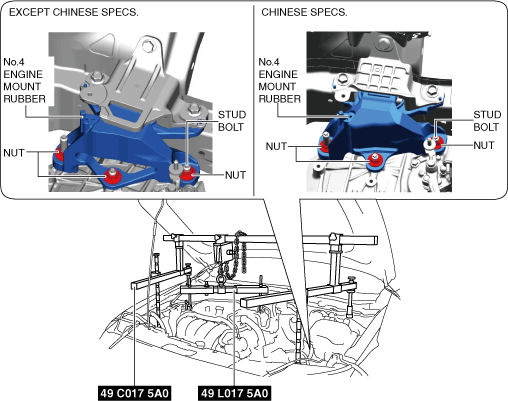
7. Lift up the transaxle using the SSTs, pass the stud bolt through the No.4 engine mount rubber, and temporarily tighten the No.4 engine mount rubber installation nuts.
ac30zw00004135
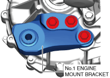
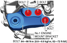
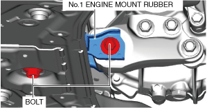
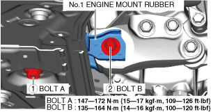
8. Install the No.1 engine mount bracket, and tighten the installation bolts in the order shown in the figure.