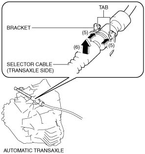
(7) While pressing the bracket tab in the direction of the arrow (5) shown in the figure, lift up the cable outer end (transaxle side) in the direction of the arrow (6) shown in the figure to detach the bracket tab from the cable outer end (transaxle side).
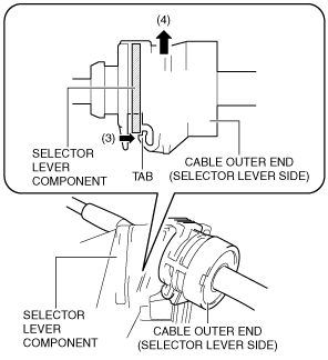
(12) While pressing the cable outer end tab (selector lever side) in the direction of the arrow (3) shown in the figure, lift up cable outer end (selector lever side) in the direction of the arrow (4) shown in the figure to detach the cable outer end tab (selector lever side) from the selector lever component.
am6xuw00009725
(13) Disconnect the cable outer end (selector lever side) from the selector lever component.
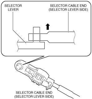
(14) Disconnect the selector cable end (selector lever side) from the selector lever.
am6xuw00009726
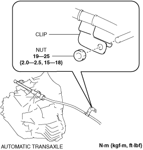
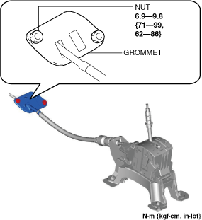
5. Disconnect the grommet as shown in the figure and remove the nuts.
ac30zw00000663
6. Pull out the selector cable from inside the cabin and remove it.
7. Install in the reverse order of removal.
Selector Cable End (Transaxle Side) Installation Note
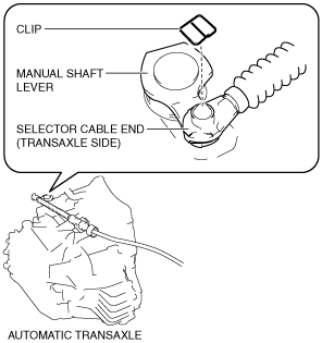
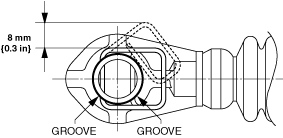
1. Install a clip to the groove of the selector cable end (transaxle side).
Caution
• Pull the clip within the range shown in the figure. If the clip is pulled excessively, it could deform and no longer function.
ac5uuw00009246
Cable Outer End (Transaxle Side) Installation Note
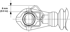
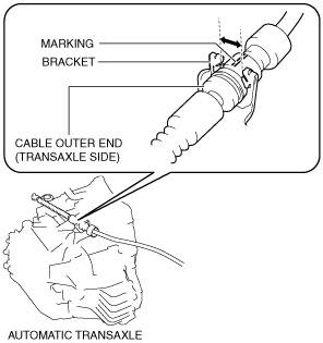
1. Assemble the cable outer end (transaxle side) to the bracket so that the marking is in the area of the arrow shown in the figure.
am6xuw00009732
Selector Cable (Selector Lever Side) Installation Note
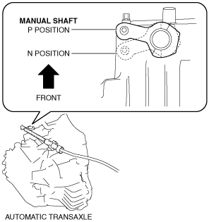
1. Verify that the selector lever is in the P position.
2. Verify that the manual shaft is in the P position.
am3uuw00011063
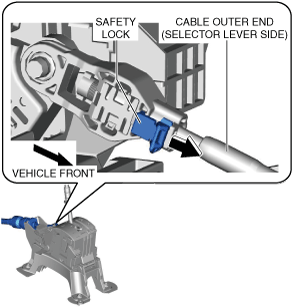
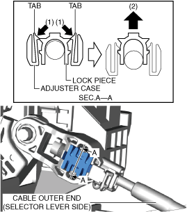
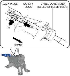
3. Press in the lock piece in the direction of the arrow (1) shown in the figure, press in the safety lock in the direction of the arrow (2) shown in the figure, and lock it.