1. : Mazda SST number
2. : Global SST number
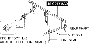
1: 49 C017 5A0
2: –
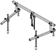
Engine support set
1: 49 UN30 3050
2: 303–050
Engine lifting bracket
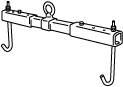
1: 49 L017 5A0
2: –
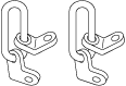
Support hanger
AUTOMATIC TRANSAXLE REMOVAL/INSTALLATION [ET6A-EL (SKYACTIV-X 2.0)]
id0517n31172o5
Special Service Tool (SST)
|
1. : Mazda SST number
2. : Global SST number
|
|||||
|
1: 49 C017 5A0
2: –
Engine support set
|
|
1: 49 UN30 3050
2: 303–050
Engine lifting bracket
|
|
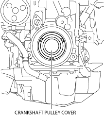
1: 49 L017 5A0
2: –
Support hanger
|
|
Removal
1. When replacing the automatic transaxle, perform TCM configuration. (See TCM CONFIGURATION [ET6A-EL, ET6AX-EL].)
2. Disconnect the negative battery terminal and wait for 1 min or more. (See NEGATIVE BATTERY TERMINAL DISCONNECTION/CONNECTION [(E)].)
3. Remove the engine cover. (See ENGINE COVER REMOVAL/INSTALLATION [SKYACTIV-X 2.0].)
4. Remove the side wall. (See SIDE WALL REMOVAL/INSTALLATION [SKYACTIV-X 2.0].)
5. Remove the following parts as a single unit. (See AIR CLEANER REMOVAL/INSTALLATION [SKYACTIV-X 2.0].)
6. Remove the battery. (See BATTERY REMOVAL/INSTALLATION [SKYACTIV-X 2.0].)
7. Remove the battery tray and PCM component as a single unit. (See BATTERY REMOVAL/INSTALLATION [SKYACTIV-X 2.0].)
8. Remove the front under cover No.2. (See FRONT UNDER COVER No.2 REMOVAL/INSTALLATION.)
9. Remove the front under cover No.1. (See FRONT UNDER COVER No.1 REMOVAL/INSTALLATION.)
10. Remove the front deflector. (See DEFLECTOR REMOVAL/INSTALLATION.)
11. Remove the front splash shield. (See SPLASH SHIELD REMOVAL/INSTALLATION.)
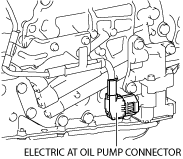
12. Disconnect the electric AT oil pump connector.
am3zzw00027355
|
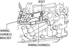
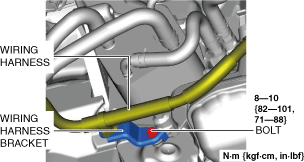
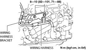
13. Remove the bolts and set the wiring harness and wiring harness bracket in a place which does not interfere with servicing.
am3zzw00027356
|
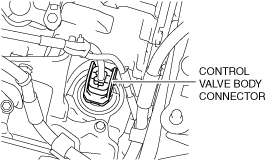
14. Disconnect the control valve body connector.
am3zzw00022344
|
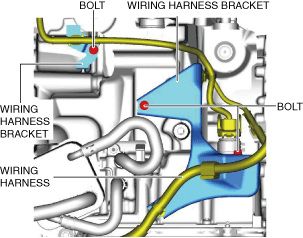
15. Remove the bolts and set the wiring harness and wiring harness brackets in a place which does not interfere with servicing.
am3zzw00032527
|
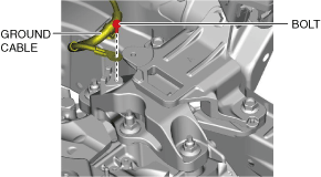
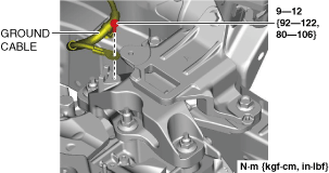
16. Disconnect the ground cable.
am3zzw00031931
|
17. Disconnect the selector cable from the transaxle. (See SELECTOR CABLE REMOVAL/INSTALLATION [(E)].)
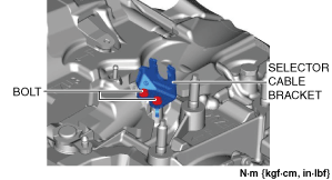
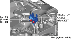
18. Remove the selector cable bracket.
am3zzw00031932
|
19. Drain the engine coolant. (See ENGINE COOLANT REPLACEMENT [SKYACTIV-X 2.0].)
20. Remove the EGR cooler. (See EGR COOLER REMOVAL/INSTALLATION [SKYACTIV-X 2.0].)
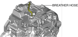
21. Disconnect the breather hose from the transaxle.
am3zzw00031933
|
22. Remove the joint cover. (See STEERING WHEEL AND COLUMN REMOVAL/INSTALLATION [(E)].)
23. Disconnect the intermediate shaft (lower side) from the steering gear and linkage. (See INTERMEDIATE SHAFT REMOVAL/INSTALLATION [(E)].)
24. Remove the tunnel cover. (See MIDDLE PIPE REMOVAL/INSTALLATION [SKYACTIV-X 2.0].)
25. Remove the front tires. (See WHEEL AND TIRE REMOVAL/INSTALLATION.)
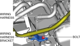
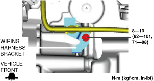
26. Remove the bolt and set the wiring harness and wiring harness bracket in a place which does not interfere with servicing.
am3zzw00031934
|
27. Drain the ATF. (See AUTOMATIC TRANSAXLE FLUID (ATF) REPLACEMENT [ET6A-EL, ET6AX-EL (E)].)
28. Disconnect the water hoses from the oil cooler. (See OIL COOLER REMOVAL/INSTALLATION [ET6A-EL, ET6AX-EL (SKYACTIV-X 2.0)].)
29. Remove the starter. (See STARTER REMOVAL/INSTALLATION [SKYACTIV-X 2.0].)
30. Remove the crankshaft pulley cover.
ac30zw00001946
|
31. Hold the crankshaft pulley to prevent drive plate from rotating.
am3uuw00002582
|
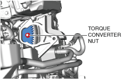
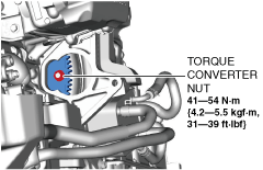
32. Remove the torque converter nuts from the starter installation hole.
am3zzw00031936
|
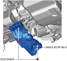
33. Remove the insulator No.6.
am3zzw00032285
|
34. Disconnect the tie-rod ends from the steering knuckles. (See TIE-ROD END REPLACEMENT [(E)].)
35. Disconnect the front lower arm ball joints from the steering knuckle. (See FRONT LOWER ARM REMOVAL/INSTALLATION [(E)].)
36. Disconnect the front drive shaft (LH) from the transaxle. (See FRONT DRIVE SHAFT REMOVAL/INSTALLATION [(E)].)
37. Disconnect the front drive shaft (RH) from the transaxle. (See FRONT DRIVE SHAFT REMOVAL/INSTALLATION [(E)].)
38. Disconnect the ground plate. (See GROUND PLATE DISCONNECTION/CONNECTION.)
39. Remove the front crossmember component and No.1 engine mount rubber as a single unit. (See FRONT CROSSMEMBER REMOVAL/INSTALLATION [(E)].)
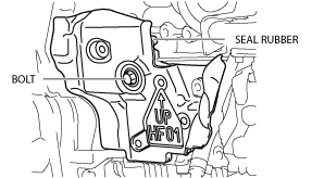
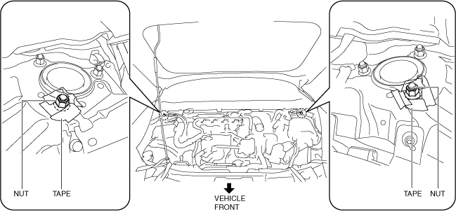
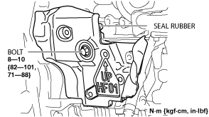
40. Remove the seal rubber.
ac30zw00001947
|
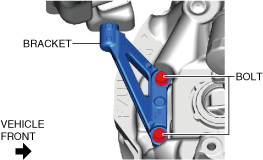
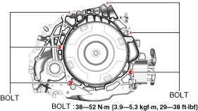
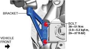
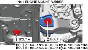
41. Remove the bolts shown in the figure.
am3zzw00031939
|
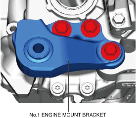
42. Remove the No.1 engine mount bracket from the transaxle.
am3zzw00031940
|
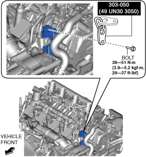
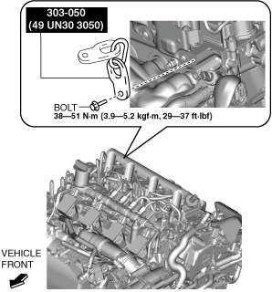
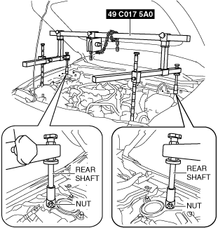
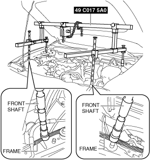
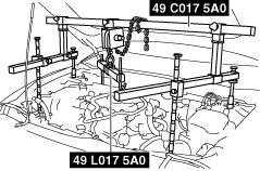
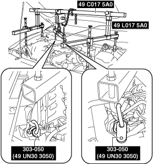
43. Install the SST using the following procedures.
ac5uuw00006422
|
am3zzw00022349
|
Engine front side
am3zzw00032286
|
Engine rear side
am3zzw00032287
|
am3zzw00022352
|
am3zzw00022353
|
am3zzw00031943
|
am3zzw00031944
|
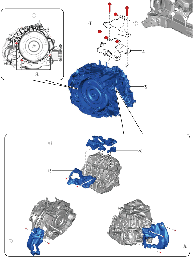
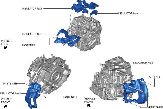
44. Remove in the order shown in the figure.
ac30zw00004138
|
|
1
|
Transaxle mounting bolts (upper side)
|
|
2
|
No.4 engine mount bracket
|
|
3
|
No.4 engine mount rubber
|
|
4
|
Transaxle mounting bolts (lower side)
|
|
5
|
Transaxle
|
|
6
|
Insulator No.1
|
|
7
|
Insulator No.2
|
|
8
|
Insulator No.3
|
|
9
|
Insulator No.4
|
|
10
|
Insulator No.5
|
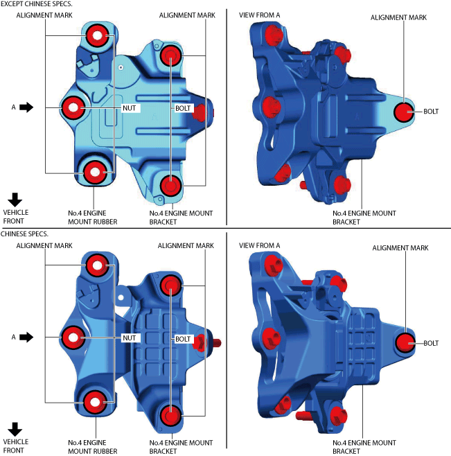
No.4 engine mount rubber and No.4 engine mount bracket removal note
1. Place alignment marks on the locations shown in the figure so that they can be assembled to the same positions as before removal.
ac30zw00004139
|
2. Remove the No.4 engine mount rubber and the No.4 engine mount bracket.
Transaxle mounting bolt removal note
1. Adjust the SST and lean the engine toward the transaxle.
am3zzw00031943
|
2. Support the transaxle on a jack.
am3uuw00002584
|
3. Remove the transaxle mounting bolts (lower side).
4. Remove the transaxle.
Installation
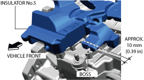
1. Install the insulators using the following procedure.
am3zzw00032289
|
ac30zw00004675
|
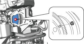
2. Verify that the torque converter stud bolts are inserted into the drive plate bolt holes from the starter installation hole.
am3zzw00032290
|
3. Install the transaxle mounting bolts.
am3zzw00032291
|
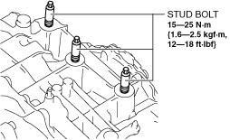
4. Tighten the stud bolts for the transaxle.
am3zzw00031948
|
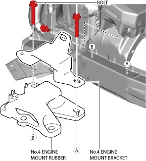
5. Install the No.4 engine mount bracket and the No.4 engine mount rubber, and temporarily tighten the bolts shown in the figure.
ac30zw00004140
|
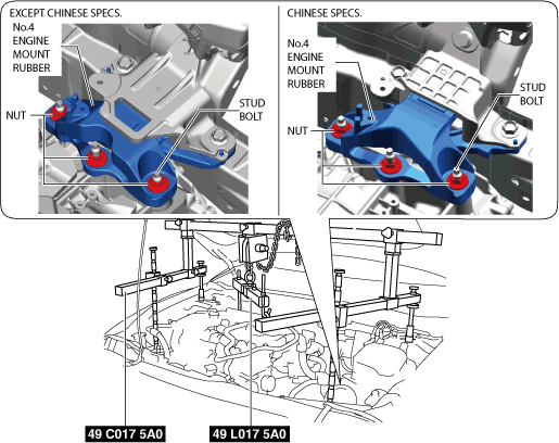
6. Lift up the transaxle using the SSTs, pass the stud bolt through the No.4 engine mount rubber, and temporarily tighten the No.4 engine mount rubber installation nuts.
ac30zw00004141
|
7. Temporarily tighten the bolts shown in the figure.
am3zzw00031951
|
8. Completely tighten the bolts shown in the figure.
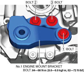
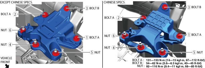
9. Install the No.1 engine mount bracket, and tighten the installation bolts in the order shown in the figure.
am3zzw00031952
|
10. Install the front crossmember component and No.1 engine mount rubber as a single unit. (See FRONT CROSSMEMBER REMOVAL/INSTALLATION [(E)].)
11. Connect the ground plate. (See GROUND PLATE DISCONNECTION/CONNECTION.)
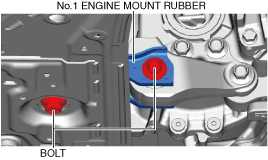
12. Temporarily tighten the No.1 engine mount rubber installation bolts.
am3zzw00031953
|
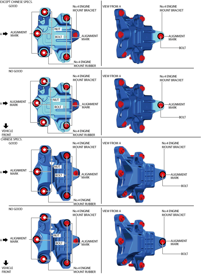
13. Align the nuts and bolts shown in the figure with the alignment marks.
ac30zw00004142
|
14. Tighten the No.4 engine mount rubber installation nuts and the No.4 engine mount bracket installation bolts in the order shown in the figure.
ac30zw00004708
|
15. Remove the SST (49 C017 5A0).
16. Tighten the No.1 engine mount rubber installation bolts in the order shown in the figure.
am3zzw00031956
|
17. Install the coolant reserve tank. (See COOLANT RESERVE TANK REMOVAL/INSTALLATION [SKYACTIV-X 2.0].)
18. Fix the crankshaft pulley to lock the torque converter against rotation.
am3uuw00002582
|
19. Tighten the torque converter installation nuts.
am3zzw00031957
|
20. Install the insulator No.6.
am3zzw00032285
|
21. Install the crankshaft pulley cover.
ac30zw00001946
|
22. Install the seal rubber.
ac30zw00001948
|
23. Install the starter. (See STARTER REMOVAL/INSTALLATION [SKYACTIV-X 2.0].)
24. Connect the front drive shaft (RH) to the transaxle. (See FRONT DRIVE SHAFT REMOVAL/INSTALLATION [(E)].)
25. Connect the front drive shaft (LH) to the transaxle. (See FRONT DRIVE SHAFT REMOVAL/INSTALLATION [(E)].)
26. Connect the front lower arm ball joint to the steering knuckles. (See FRONT LOWER ARM REMOVAL/INSTALLATION [(E)].)
27. Connect the tie-rod ends to the steering knuckles. (See TIE-ROD END REPLACEMENT [(E)].)
28. Connect the water hose to the oil cooler. (See OIL COOLER REMOVAL/INSTALLATION [ET6A-EL, ET6AX-EL (SKYACTIV-X 2.0)].)
29. Install the wiring harness bracket.
am3zzw00031959
|
30. Install the tunnel cover. (See MIDDLE PIPE REMOVAL/INSTALLATION [SKYACTIV-X 2.0].)
31. Install the front tires. (See WHEEL AND TIRE REMOVAL/INSTALLATION.)
32. Connect the intermediate shaft (lower side) to the steering gear and linkage. (See INTERMEDIATE SHAFT REMOVAL/INSTALLATION [(E)].)
33. Install the joint cover. (See STEERING WHEEL AND COLUMN REMOVAL/INSTALLATION [(E)].)
34. Connect the breather hose to the transaxle.
am3zzw00031933
|
35. Install the EGR cooler. (See EGR COOLER REMOVAL/INSTALLATION [SKYACTIV-X 2.0].)
36. Install the selector cable bracket.
am3zzw00031960
|
37. Connect the selector cable to the transaxle. (See SELECTOR CABLE REMOVAL/INSTALLATION [(E)].)
38. Connect the ground cable to the No.4 engine mount rubber.
am3zzw00031961
|
39. Install the wiring harness bracket.
am3zzw00031962
|
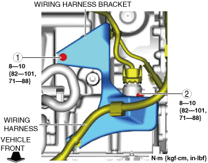
40. Tighten the wiring harness bracket installation bolts in the order shown in the figure.
am3zzw00031963
|
41. Connect the control valve body connector.
am3zzw00022344
|
42. Install the wiring harness bracket.
am3zzw00027358
|
43. Connect the electric AT oil pump connector.
am3zzw00027355
|
44. Install the front splash shield. (See SPLASH SHIELD REMOVAL/INSTALLATION.)
45. Install the front deflector. (See DEFLECTOR REMOVAL/INSTALLATION.)
46. Install the battery tray and PCM component as a single unit. (See BATTERY REMOVAL/INSTALLATION [SKYACTIV-X 2.0].)
47. Install the battery. (See BATTERY REMOVAL/INSTALLATION [SKYACTIV-X 2.0].)
48. Install the following parts as a single unit. (See AIR CLEANER REMOVAL/INSTALLATION [SKYACTIV-X 2.0].)
49. Install the side wall. (See SIDE WALL REMOVAL/INSTALLATION [SKYACTIV-X 2.0].)
50. Install the engine cover. (See ENGINE COVER REMOVAL/INSTALLATION [SKYACTIV-X 2.0].)
51. Connect the negative battery terminal. (See NEGATIVE BATTERY TERMINAL DISCONNECTION/CONNECTION [(E)].)
52. Refill the engine coolant. (See AUTOMATIC TRANSAXLE FLUID (ATF) REPLACEMENT [ET6A-EL, ET6AX-EL (E)].)
53. Add the ATF. (See AUTOMATIC TRANSAXLE FLUID (ATF) REPLACEMENT [ET6A-EL, ET6AX-EL (E)].)
54. Install the front under cover No.1. (See FRONT UNDER COVER No.1 REMOVAL/INSTALLATION.)
55. Install the front under cover No.2. (See FRONT UNDER COVER No.2 REMOVAL/INSTALLATION.)
56. If the automatic transaxle has been replaced, perform TCM configuration. (See TCM CONFIGURATION [ET6A-EL, ET6AX-EL].)
57. If the automatic transaxle has been replaced, perform the “Initial Learning”. (See INITIAL LEARNING [ET6A-EL, ET6AX-EL (E)].)
58. Perform the “Mechanical System Test”. (See MECHANICAL SYSTEM TEST [ET6A-EL, ET6AX-EL (E)].)