 |
ac30zw00004976
ENGINE REAR COVER REMOVAL/INSTALLATION [SKYACTIV-X 2.0]
id0110hf880000
Replacement part
|
Vacuum hose
Quantity: 1
Location of use: Supercharger component
|
Gasket
Quantity: 1
Location of use: Engine rear cover (upper)
|
Rear oil seal
Quantity: 1
Location of use: Engine rear cover (lower)
|
|
Clamp
Quantity: 1
Location of use: Supercharger component
|
—
|
—
|
Oil and chemical type
|
Sealant
Type: TB1217D
|
Engine Rear Cover (Upper) Removal/Installation
1. Disconnect the negative battery terminal. (See NEGATIVE BATTERY TERMINAL DISCONNECTION/CONNECTION [(E)].)
2. Remove the engine cover. (See ENGINE COVER REMOVAL/INSTALLATION [SKYACTIV-X 2.0].)
3. Remove the following parts. (See SIDE WALL REMOVAL/INSTALLATION [SKYACTIV-X 2.0].)
4. Remove the following parts as a single unit: (See AIR CLEANER REMOVAL/INSTALLATION [SKYACTIV-X 2.0].)
5. Remove the resonance chamber.(See AIR CLEANER REMOVAL/INSTALLATION [SKYACTIV-X 2.0].)
6. Remove the battery tray and PCM as a single unit. (See BATTERY REMOVAL/INSTALLATION [SKYACTIV-X 2.0].)
7. Disconnect the evaporative hose No.1 from the catch tank. (See PURGE SOLENOID VALVE REMOVAL/INSTALLATION [SKYACTIV-X 2.0].)
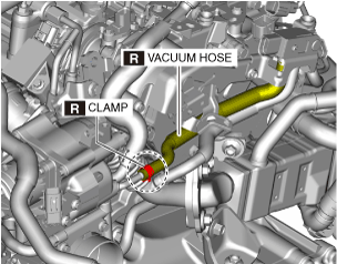
8. Disconnect the vacuum hose shown in the figure.
ac30zw00004976
|
9. Remove the EGR pipe and EGR pressure sensor as a single unit. (See EGR PIPE REMOVAL/INSTALLATION [SKYACTIV-X 2.0].) (See EGR PRESSURE SENSOR REMOVAL/INSTALLATION [SKYACTIV-X 2.0].)
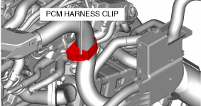
10. Disconnect the PCM wiring harness clip.
am3zzw00035780
|
11. Disconnect the connectors of the following parts:
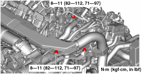
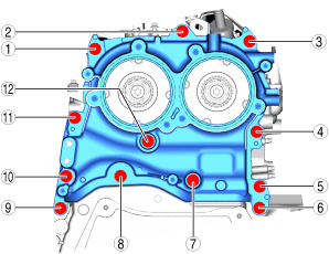
12. Remove the bolts shown in the figure.
am3zzw00035781
|
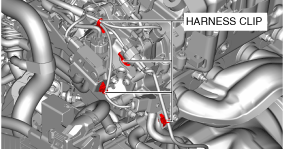
13. Detach the wiring harness clips shown in the figure.
am3zzw00035782
|
14. Set the GPF pressure sensor and bracket aside as a single unit. (See GPF PRESSURE SENSOR REMOVAL/INSTALLATION [SKYACTIV-X 2.0].)
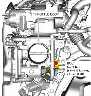
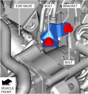
15. Remove the bolt shown in the figure.
am3zzw00035917
|
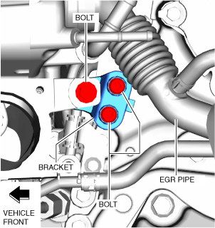
16. Remove the bracket shown in the figure. (See SUPERCHARGER REMOVAL/INSTALLATION [SKYACTIV-X 2.0].)
am3zzw00035918
|
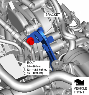
17. Remove the bracket shown in the figure. (See SUPERCHARGER REMOVAL/INSTALLATION [SKYACTIV-X 2.0].)
am3zzw00035919
|
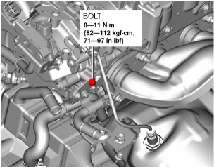
18. Remove the bracket shown in the figure.
am3zzw00035920
|
19. Remove the water pipe bolt shown in the figure.
am3zzw00035921
|
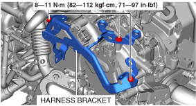
20. Remove the wiring harness bracket shown in the figure.
am3zzw00036893
|
21. Set the EGR cooler aside. (See EGR COOLER REMOVAL/INSTALLATION [SKYACTIV-X 2.0].)
22. Remove the intake electric variable valve timing motor/driver and the exhaust electric variable valve timing motor/driver. (See ELECTRIC VARIABLE VALVE TIMING MOTOR/DRIVER REMOVAL/INSTALLATION [SKYACTIV-X 2.0].)
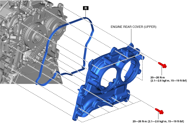
23. Remove the engine rear cover (upper).
am3zzw00035784
|
24. Install in the reverse order of removal. (See Engine rear cover (upper) installation note.)
Engine rear cover (upper) installation note
1. Insert the engine rear cover (upper) gasket into the groove of the engine rear cover (upper).
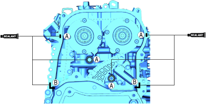
2. Apply silicone sealant (TB1217D) to the areas shown in the figure.
a59cjw00001097
|
3. Install the engine rear cover (upper).
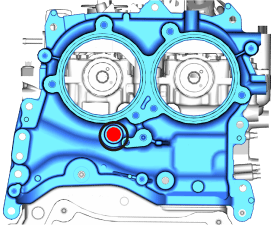
4. Temporarily tighten the engine rear cover (upper) bolts shown in the figure.
ac30zw00003114
|
5. Tighten the engine rear cover (upper) bolts in the order shown in the figure.
ac30zw00003115
|
Engine Rear Cover (Lower) Removal/Installation
1. Remove the engine rear cover (upper). (See Engine Rear Cover (Upper) Removal/Installation)
2. Remove the oil pan. (See OIL PAN REMOVAL/INSTALLATION [SKYACTIV-X 2.0].)
3. Remove the transaxle. (See MANUAL TRANSAXLE REMOVAL/INSTALLATION [C66M-R (SKYACTIV-X 2.0)].(MTX_2WD))(See MANUAL TRANSAXLE REMOVAL/INSTALLATION [C66MX-R (SKYACTIV-X 2.0)].(MTX_AWD))(See AUTOMATIC TRANSAXLE REMOVAL/INSTALLATION [ET6A-EL (SKYACTIV-X 2.0)].(ATX_2WD))(See AUTOMATIC TRANSAXLE REMOVAL/INSTALLATION [ET6AX-EL (SKYACTIV-X 2.0)].(ATX_AWD))
4. Remove the flywheel (MTX) or the drive plate (ATX). (See CLUTCH UNIT REMOVAL/INSTALLATION [C66M-R]. (MTX))(See DRIVE PLATE REMOVAL/INSTALLATION [ET6A-EL, ET6AX-EL (E)]. (ATX))
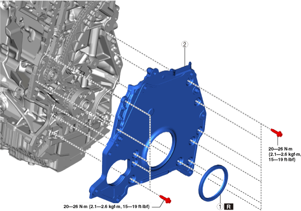
5. Remove in the order indicated in the table.
6. Install in the reverse order of removal.
ac30zw00004774
|
|
1
|
Rear oil seal (See REAR OIL SEAL REPLACEMENT [SKYACTIV-X 2.0].)
|
|
2
|
Engine rear cover (lower)
|
Engine rear cover (lower) removal note
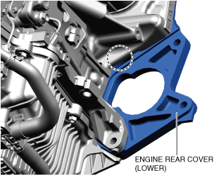
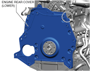
1. Insert a tape-wrapped flathead screwdriver into the positions shown in the figures, and push open a gap between the cylinder block and the rear cover.
am3zzw00037023
|
am3zzw00037024
|
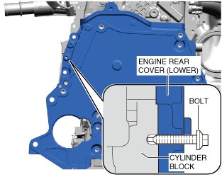
2. Insert a M6 bolt (bolt stem length is 30 mm {1.2 in} or more and with no threads on end) to the position shown in the figure and screw it to push open a gap between the cylinder block and the rear cover.
am3zzw00037025
|
Engine rear cover (lower) installation note
ac30zw00005262
|
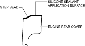
1. Completely clean and remove oil, dirt, silicone sealant or other foreign matter that may be adhering to the engine rear cover (lower), cylinder head, and cylinder block.
2. Degrease the silicone sealant application surface and the step bead.
3. Insert the engine rear cover (lower) gasket into the groove of the engine rear cover (lower).
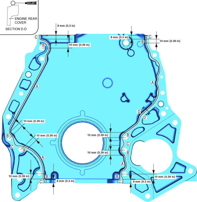
4. Apply silicone sealant (TB1217D) to the areas shown in the figure.
am3zzw00037051
|
5. Install the engine rear cover (lower).
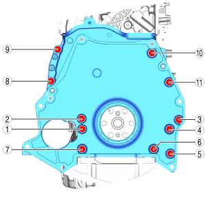
6. Tighten the engine rear cover (lower) bolts in the order shown in the figure.
am30jw00000034
|