Step
Inspection
Results
Action
1
RECORD VEHICLE STATUS WHEN DTC WAS DETECTED TO UTILIZE WITH REPEATABILITY VERIFICATION
• Record the freeze frame data/snapshot data.
-
Note
-
• Recording can be facilitated using the screen capture function of the PC.
—
Go to the next step.
2
VERIFY RELATED REPAIR INFORMATION OR SERVICE INFORMATION AVAILABILITY
• Verify related Service Bulletins, on-line repair information, or Service Information availability.
• Is any related Information available?
Yes
Perform repair or diagnosis according to the available information.
• If the vehicle is not repaired, go to the next step.
No
Go to the next step.
3
INSPECT FOR OTHER RELATED DTCs
• Perform the DTC inspection for the PCM.
(See DTC INSPECTION.)
• Are any other DTCs displayed?
Yes
If DTC P1142:00, P2104:00 or P2263:00 is stored:
• Go to the next step.
If DTC other than P1142:00, P2104:00 or P2263:00 is stored:
• Go to the applicable PENDING CODE or DTC inspection.
(See DTC TABLE [PCM (SKYACTIV-D)].)
No
Go to the next step.
4
DETERMINE IF MALFUNCTION IS CAUSED BY TURBOCHARGER WITH VARIABLE TURBINE GEOMETRY
• Switch the ignition off.
• Switch the ignition ON (engine on).
• Display PID TURBO_POS_ACT and simulation item TURBO_POS_DSD using the M-MDS.
(See DTC INSPECTION.)
• Operate the turbocharger with variable geometry using simulation item TURBO_POS_DSD.
• Does PID TURBO_POS_ACT change according to the simulation operation?
Yes
Go to Step 18.
No
Go to the next step.
5
INSPECT VACUUM CHAMBER FOR MALFUNCTION
• Inspect the applicable part.
• Is the part normal?
Yes
Go to the next step.
No
Replace the cylinder head cover, then go to Step 9.
6
INSPECT VACUUM PIPING
• Inspect vacuum piping at the following:
-
― Power brake unit—Vacuum pump― Vacuum pump—Check valve― Check valve—Vacuum chamber― Vacuum chamber—Turbocharger solenoid valve― Turbocharger solenoid valve—Turbocharger actuator
• Is there hose leakage or damage in the vacuum piping?
Yes
Repair or replace the malfunctioning part according to the inspection results, then go to Step 9.
No
Go to the next step.
7
INSPECT TURBOCHARGER SOLENOID VALVE FOR MALFUNCTION
• Inspect the applicable part.
• Is the part normal?
Yes
Go to the next step.
No
Replace the turbocharger solenoid valve, then go to Step 9.
8
INSPECT CHECK VALVE FOR MALFUNCTION
• Inspect the applicable part.
• Is the part normal?
Yes
Replace the turbocharger with variable turbine geometry, then go to Step 18.
No
Repair or replace the malfunctioning location and perform the repair completion verification.
9
DETERMINE IF MALFUNCTION IS CAUSED BY TURBOCHARGER WITH VARIABLE TURBINE GEOMETRY
• Switch the ignition off.
• Switch the ignition ON (engine on).
• Display PID TURBO_POS_ACT and simulation item TURBO_POS_DSD using the M-MDS.
(See DTC INSPECTION.)
• Operate the turbocharger with variable geometry using simulation item TURBO_POS_DSD.
• Does PID TURBO_POS_ACT change according to the simulation operation?
Yes
Go to the next step.
No
Replace the turbocharger with variable turbine geometry, then go to Step 18.
10
VERIFY IF METAL FRAGMENTS PENETRATED ENGINE OIL
• Drain the engine oil.
• Are there metal fragments in the drained engine oil?
Yes
Replace or overhaul the engine as a partial engine unit.
Refer to the Mazda Workshop Manual.
Go to Step 18.
No
Go to the next step.
11
REMOVE ANY ENGINE OIL IN THE PISTON CAVITY.
• Remove the glow plug.
• Hold cloth over the glow plug installation hole.
• Crank the engine and remove the engine oil from the glow plug installation hole.
—
Go to the next step.
12
INSPECT ENGINE COMPRESSION
• Inspect the engine compression.
• Are compression pressures within specification?
Yes
Go to the next step.
No
Repair or replace the malfunctioning part according to the inspection results, then go to Step 18.
13
INSPECT WATER-COOLED CHARGE AIR COOLER CORE CONDITION
• Visually inspect the water-cooled charge air cooler core condition.
• Is there any engine oil in the core of the water-cooled charge air cooler?
Yes
Blow the core of the water-cooled charge air cooler with compressed air to remove the engine oil.
Clean or replace the water-cooled charge air cooler, then go to the next step.
No
Inspect restrict in water-cooled charge air cooler coolant passage.
• If malfunction is detected:
-
― Repair or replace the malfunctioning part, then go to the next step.
• If normal:
-
― Go to the next step.
14
VERIFY CONDITION OF BOTTOM SURFACE IN INTAKE MANIFOLD
• Verify condition of bottom surface in intake manifold.
• Is there any engine oil on the bottom in the intake manifold?
Yes
Remove any engine oil on the bottom in the intake manifold, then go to the next step.
No
Go to the next step.
15
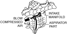
INSPECT INTAKE MANIFOLD ASPIRATOR PART FOR FOREIGN MATTER
• Blow compressed air into the intake manifold aspirator part (inside the passage) from the direction of the arrow shown in the figure and remove any foreign matter.
am3zzw00020268
|
—
Go to the next step.
16
INSPECT MAP SENSOR FOR MALFUNCTION
• Inspect the applicable part.
• Is the part normal?
Yes
Go to the next step.
No
Repair or replace the malfunctioning location and perform the repair completion verification.
17
INSPECT EXHAUST GAS PRESSURE SENSOR No.1 FOR MALFUNCTION
• Inspect the applicable part.
• Is the part normal?
Yes
Go to the next step.
No
Repair or replace the malfunctioning location and perform the repair completion verification.
18
PERFORM COMPULSORY DIESEL PARTICULATE FILTER REGENERATION AND BURN OUT ENGINE OIL IN DIESEL PARTICULATE FILTER
• Perform the "COMPULSORY DIESEL PARTICULATE FILTER REGENERATION".
-
Note
-
• When a DTC is stored, compulsory diesel particulate filter regeneration may be performed by the PCM control.(See DTC INSPECTION.)
-
― For DTCs P242F:00, the "COMPULSORY DIESEL PARTICULATE FILTER REGENERATION" will only be blocked if an excessive amount of soot is in the diesel particulate filter.
• Compulsory diesel particulate filter regeneration is performed after performing the applicable DTC troubleshooting.(See DTC TABLE [PCM (SKYACTIV-D)].) -
—
Go to the next step.
19
INSPECT ENGINE OIL LEVEL
• Inspect the engine oil level.
• Is the engine oil amount above X line on the dipstick?
Yes
Replace the engine oil.
Perform the “ENGINE OIL DATA RESET”.
Go to the next step.
No
Go to the next step.
Repair completion verification 1
VERIFY THAT VEHICLE IS REPAIRED
• Install/connect the part removed/disconnected during the troubleshooting procedure.
• Clear the DTC recorded in the memory.
(See CLEARING DTC.)
• Replicate the vehicle conditions at the time the DTC was detected using the following procedure.
-
― Perform the “FUEL INJECTOR INJECTION AMOUNT CORRECTION”.― Start the engine and warm it up completely.
-
Caution
-
• While performing this step, always operate the vehicle in a safe and lawful manner.• When the M-MDS is used to observe monitor system status while driving, be sure to have another technician with you, or record the data in the M-MDS using the PID/DATA MONITOR AND RECORD capturing function and inspect later.
― Drive the vehicle under the FREEZE FRAME DATA/snapshot data condition. -
• Perform the DTC inspection for the PCM.
(See DTC INSPECTION.)
• Is the same Pending DTC present?
Yes
Refer to the controller area network (CAN) malfunction diagnosis flow to inspect for a CAN communication error.
If the CAN communication is normal, perform the diagnosis from Step 1.
• If the malfunction recurs, replace the PCM, then go to the next step.
No
Go to the next step.
Repair completion verification 2
VERIFY IF OTHER DTCs DISPLAYED
• Perform the DTC inspection.
(See DTC INSPECTION.)
• Are any other DTCs displayed?
Yes
Repair the malfunctioning location according to the applicable DTC troubleshooting.
No
Referring to each adjustment procedure, perform fuel injector injection amount correction and then the diesel particulate filter data reset.
DTC troubleshooting completed.