|
1
|
INSPECT VEHICLE CONDITION FOR EFFECT ON MALFUNCTION
• Verify how the customer drives the vehicle by asking the customer the following:
-
― Because engine is started with accelerator pedal fully depressed, it goes into dechoke mode and fuel is not injected
• Does the engine start with the accelerator pedal fully depressed?
|
Yes
|
Explain to the customer that the vehicle is normal and give them advice on how to start the engine and a specific example of the conditions in which the engine goes into dechoke mode.
|
|
No
|
Go to the next step.
|
|
2
|
VERIFY IF MALFUNCTION CAUSE IS OVERHEATING
• Access the ECT PID using the M-MDS.
• Is the ECT PID value less than 116 °C {241 °F} during driving?
|
Yes
|
Go to the next step.
|
|
No
|
The cause of this concern could be from the cooling system overheating.
• Perform the symptom troubleshooting “COOLING SYSTEM CONCERNS-OVERHEATING”.
|
|
3
|
VERIFY DTCs
• Perform the DTC inspection for the following modules.
-
― PCM
― Mazda M Hybrid battery
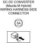
― DC-DC converter (Mazda M Hybrid)
― Integrated starter generator (ISG)
• Are any DTCs displayed?
|
Yes
|
Repair the malfunctioning location according to the applicable DTC troubleshooting.
|
|
No
|
Go to the next step.
|
|
4
|
VERIFY CURRENT INPUT SIGNAL STATUS
-
Warning
-
• While performing this step, always operate the vehicle in a safe and lawful manner.
• When the M-MDS is used to observe monitor system status while driving, be sure to have another technician with you, or record the data in the M-MDS using the PID/DATA MONITOR AND RECORD capturing function and inspect later.
• Access the following PIDs using the M-MDS:
-
― APP1
― APP2
― ECT
― ECT_VOLT
― ECT2
― ECT2_VOLT
― MAF
― A/F_SEN_CUR
― HO2S_OUT_VOLT
― SHRT_FUEL_TRIM
― LONG_FUEL_TRIM
• Do the PIDs indicate the correct values under the malfunction condition?
|
Yes
|
Go to the next step.
|
|
No
|
APP1, APP2 PIDs are not as specified:
• Inspect the APP sensor No.1 and No.2.
ECT, ECT_VOLT, ECT2, ECT2_VOLT PIDs are not as specified:
• Inspect the ECT sensor No.1 and No.2.
MAF PID is not as specified:
• Inspect the MAF sensor.
A/F_SEN_CUR, SHRT_FUEL_TRIM, LONG_FUEL_TRIM PIDs are not as specified:
• Inspect the A/F sensor.
HO2S_OUT_VOLT PID is not as specified:
Repair or replace the malfunctioning location.
• If the malfunction remains:
-
― Perform the “Action for Non-repeatable Malfunction” procedure.
|
|
5
|
DETERMINE IF MALFUNCTION CAUSE IS DRIVE-BY-WIRE CONTROL SYSTEM OR OTHER
• Will the engine run smoothly at part throttle?
|
Yes
|
Go to Step 7.
|
|
No
|
Go to the next step.
|
|
6
|
INSPECT DRIVE-BY-WIRE CONTROL SYSTEM OPERATION
• Perform the Electronic Control Throttle Operation Inspection.
• Does the drive-by-wire control system work properly?
|
Yes
|
Visually inspect the throttle body (damage/scratching).
• If there is any malfunction:
-
― Repair or replace the malfunctioning location and perform the repair completion verification.
• If there is no malfunction:
-
― Go to the next step.
|
|
No
|
Repair or replace the malfunctioning location and perform the repair completion verification.
|
|
7
|
INSPECT PURGE CONTROL SYSTEM OPERATION
• Perform the Purge Control System Inspection.
• Does the purge solenoid valve work properly?
|
Yes
|
Go to the next step.
|
|
No
|
Repair or replace the malfunctioning location and perform the repair completion verification.
|
|
8
|
VERIFY IF MALFUNCTION CAUSE IS MAF SENSOR SIGNAL
-
Note
-
• If the inspection in Step 8 is performed, the PCM detects a DTC and performs fail-safe control. After performing the inspection, clear DTCs using the M-MDS.
• Switch the ignition off.
• Disconnect the MAF sensor/IAT sensor No.1 connector.
• Start the engine.
• Does the engine start normally?
|
Yes
|
Clean the MAF sensor.
Verify that the symptom is solved.
• If the symptom remains, inspect the MAF sensor related wiring harness and connector.
-
― If there is any malfunction:
-
• Repair or replace the malfunctioning location and perform the repair completion verification.
― If there is no malfunction:
-
• Replace the MAF sensor/IAT sensor No.1 and perform the repair completion verification.
|
|
No
|
Go to the next step.
|
|
9
|
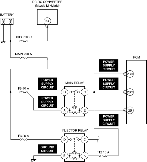
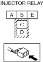
INSPECT INJECTOR RELAY FOR MALFUNCTION
• Inspect the applicable part.
• Is the part normal?
|
Yes
|
Go to the next step.
|
|
No
|
Repair or replace the malfunctioning location and perform the repair completion verification.
|
|
10
|
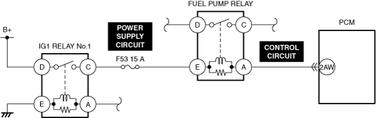
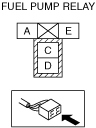
INSPECT FUEL PUMP RELAY FOR MALFUNCTION
• Inspect the applicable part.
• Is the part normal?
|
Yes
|
Go to the next step.
|
|
No
|
Repair or replace the malfunctioning location and perform the repair completion verification.
|
|
11
|
INSPECT F53 15 A FUSE
• Remove the F53 15 A fuse.
• Inspect the F53 15 A fuse.
• Is the fuse normal?
|
Yes
|
Reinstall the F53 15 A fuse, then go to the next step.
|
|
No
|
Replace the F53 15 A fuse and perform the repair completion verification.
|
|
12
|
INSPECT FUEL PUMP RELAY POWER SUPPLY CIRCUIT FOR SHORT AND OPEN CIRCUIT
• Inspect the applicable circuit for short and open circuit.
• Is the circuit normal?
|
Yes
|
Go to the next step.
|
|
No
|
Repair or replace the malfunctioning location and perform the repair completion verification.
|
|
13
|
INSPECT FUEL PUMP RELAY CONTROL CIRCUIT FOR SHORT AND OPEN CIRCUIT
• Inspect the applicable circuit for short and open circuit.
• Is the circuit normal?
|
Yes
|
Go to the next step.
|
|
No
|
Repair or replace the malfunctioning location and perform the repair completion verification.
|
|
14
|
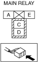
INSPECT MAIN RELAY POWER SUPPLY CIRCUIT FOR SHORT TO GROUND AND OPEN CIRCUIT
• Inspect the power supply circuit for an open circuit and short to ground.
• Is the circuit normal?
|
Yes
|
Go to the next step.
|
|
No
|
Repair or replace the malfunctioning location and perform the repair completion verification.
|
|
15
|
INSPECT PCM POWER SUPPLY CIRCUIT FOR SHORT AND OPEN CIRCUIT
• Inspect the applicable circuit for short and open circuit.
• Is the circuit normal?
|
Yes
|
Go to the next step.
|
|
No
|
Repair or replace the malfunctioning location and perform the repair completion verification.
|
|
16
|
INSPECT F12 15 A FUSE
• Remove the F12 15 A fuse.
• Inspect the F12 15 A fuse.
• Is the fuse normal?
|
Yes
|
Reinstall the F12 15 A fuse, then go to the next step.
|
|
No
|
Replace the F12 15 A fuse and perform the repair completion verification.
|
|
17
|
INSPECT INJECTOR RELAY POWER SUPPLY CIRCUIT FOR SHORT AND OPEN CIRCUIT
• Inspect the applicable circuit for short and open circuit.
• Is the circuit normal?
|
Yes
|
Go to the next step.
|
|
No
|
Repair or replace the malfunctioning location and perform the repair completion verification.
|
|
18
|
INSPECT INJECTOR RELAY GROUND CIRCUIT FOR OPEN CIRCUIT
• Inspect the applicable circuit for open circuit.
• Is the circuit normal?
|
Yes
|
Go to the next step.
|
|
No
|
Repair or replace the malfunctioning location and perform the repair completion verification.
|
|
19
|
INSPECT RELATED PART CONDITION
• Inspect the following:
-
― Fuel quality (proper octane, contamination, winter/summer blend)
― Intake-air system leakage or restriction
― Electrical connectors connection
― Poor connection for PCM ground and body ground
― Fuses
― Fuel leakage
― Vacuum leakage
― CKP sensor and exhaust CMP sensor
-
• Damaged trigger wheel exhaust camshaft
• Is there any malfunction?
|
Yes
|
Repair or replace the malfunctioning location and perform the repair completion verification.
|
|
No
|
Go to the next step.
|
|
20
|
INSPECT FUEL PRESSURE (HIGH-SIDE)
• Start the engine and warm it up completely.
• Access the FUEL_PRES PID using the M-MDS at idle.
• Is the FUEL_PRES PID value within specification?
Specification:
• Approx. 40—60 MPa {408—611 kgf/cm2, 5,802—8,702 psi}
|
Yes
|
Go to Step 22.
|
|
No
|
FUEL_PRES PID value is lower than 40 MPa {408 kgf/cm2, 5,802 psi}:
• Inspect the following:
-
― Fuel leakage at the fuel line and fuel injector
― Fuel pump
-
• Perform the Fuel Pump (Low-pressure Side) Operation Inspection.
― High fuel pressure sensor
― High pressure fuel pump
• If there is any malfunction:
-
― Repair or replace the malfunctioning location and perform the repair completion verification.
• If there is no malfunction:
-
― Go to the next step.
FUEL_PRES PID value is higher than 60 MPa {611 kgf/cm2, 8,702 psi}:
• Go to the next step.
|
|
21
|
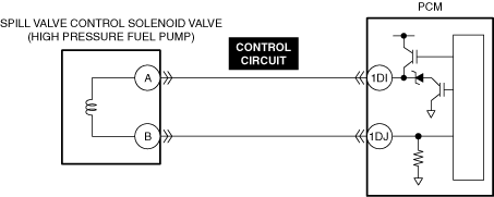
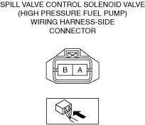
INSPECT SPILL VALVE CONTROL SOLENOID VALVE CONTROL CIRCUIT FOR SHORT TO GROUND
• Inspect the applicable circuit for a short to ground.
• Is the circuit normal?
|
Yes
|
Replace the high pressure fuel pump and perform the repair completion verification.
|
|
No
|
Repair or replace the malfunctioning location and perform the repair completion verification.
|
|
22
|
INSPECT FUEL PRESSURE (LOW-SIDE)
• Connect the fuel pressure gauge between fuel pump and high pressure fuel pump.
• Measure the low side fuel pressure.
• Is the low side fuel pressure within specification?
Specification:
• 545—695 kPa {5.56—7.08 kgf/cm2, 79.1—100.0 psi}
|
Yes
|
Go to the next step.
|
|
No
|
Inspect the following:
• Fuel line restriction
• Fuel filter clogged
-
― If there is any malfunction:
-
• Repair or replace the malfunctioning location and perform the repair completion verification.
― If there is no malfunction:
-
• Replace the fuel pump unit and perform the repair completion verification.
|
|
23
|
INSPECT FUEL INJECTOR OPERATION
• Perform the Fuel Injector Operation Inspection.
• Do the fuel injectors operate properly?
|
Yes
|
Go to the next step.
|
|
No
|
Repair or replace the malfunctioning location and perform the repair completion verification.
|
|
24
|
INSPECT FUEL TANK
• Is vapor occurring?
|
Yes
|
Replace the fuel tank and perform the repair completion verification.
|
|
No
|
Go to the next step.
|
|
25
|
INSPECT HIGH PRESSURE FUEL PUMP
• Inspect the high pressure fuel pump.
• Is vapor occurring?
|
Yes
|
Replace the high pressure fuel pump and perform the repair completion verification.
|
|
No
|
Go to the next step.
|
|
26
|
INSPECT ENGINE COMPRESSION
• Measure the compression pressure for each cylinder.
• Are compression pressures within specification?
|
Yes
|
Go to Step 31.
|
|
No
|
Go to the next step.
|
|
27
|
INSPECT INTAKE ELECTRIC VARIABLE VALVE TIMING DRIVER OR EXHAUST ELECTRIC VARIABLE VALVE TIMING DRIVER FOR MALFUNCTION
• Inspect the applicable part.
• Is the part normal?
|
Yes
|
Go to the next step.
|
|
No
|
Repair or replace the malfunctioning location and perform the repair completion verification.
|
|
28
|
INSPECT INTAKE ELECTRIC VARIABLE VALVE TIMING MOTOR OR EXHAUST ELECTRIC VARIABLE VALVE TIMING MOTOR FOR MALFUNCTION
• Inspect the applicable part.
• Is the part normal?
|
Yes
|
Go to the next step.
|
|
No
|
Repair or replace the malfunctioning location and perform the repair completion verification.
|
|
29
|
INSPECT INTAKE ELECTRIC VARIABLE VALVE TIMING ACTUATOR OR EXHAUST ELECTRIC VARIABLE VALVE TIMING ACTUATOR FOR MALFUNCTION
• Inspect the applicable part.
• Is the part normal?
|
Yes
|
Go to the next step.
|
|
No
|
Repair or replace the malfunctioning location and perform the repair completion verification.
|
|
30
|
INSPECT FOR MALFUNCTION DUE TO DEVIATED VALVE TIMING
• Inspect the valve timing (timing chain installation condition).
• Is the valve timing normal?
|
Yes
|
Inspect for the following engine internal parts:
• Cylinder
• Piston ring
• Intake valve
• Exhaust valve
• Such as cylinder head gasket
-
― If there is any malfunction:
-
• Repair or replace the malfunctioning location and perform the repair completion verification.
|
|
No
|
Adjust the valve timing to the correct timing and perform the repair completion verification.
|
|
31
|
INSPECT IGNITION SYSTEM OPERATION
-
Note
-
• Because the malfunction may have been resolved by removing the carbon adhered to the spark plug during the spark inspection for the spark plug, verify that the repairs have been completed.
• Perform the Spark Test.
• Is a strong blue spark visible at each cylinder?
|
Yes
|
Go to the next step.
|
|
No
|
Repair or replace the malfunctioning location and perform the repair completion verification.
|
|
32
|
INSPECT EXHAUST SYSTEM FOR RESTRICTION
• Inspect for restriction in the exhaust system and the catalytic converter.
• Is there any restriction?
|
Yes
|
Repair or replace the malfunctioning location and perform the repair completion verification.
|
|
No
|
Go to the next step.
|
|
33
|
INSPECT IF MALFUNCTION CAUSE IS PCV VALVE OR INJECTOR DRIVER (PCM INTEGRATED)
• Is there any malfunction?
|
Yes
|
Replace the PCV valve and perform the repair completion verification.
|
|
No
|
Injector driver malfunction.
If the problem remains, overhaul the engine and perform the repair completion verification.
|
|
Repair completion verification 1
|
VERIFY THAT VEHICLE IS REPAIRED
• Install/connect the part removed/disconnected during the troubleshooting procedure.
• Has the malfunction symptom been eliminated?
|
Yes
|
Complete the symptom troubleshooting. (Explain contents of repair to customer)
|
|
No
|
Refer to the controller area network (CAN) malfunction diagnosis flow to inspect for a CAN communication error.
• If the CAN communication is normal, perform the diagnosis from Step 1.
-
― If the malfunction recurs, go to the next step.
|
|
Repair completion verification 2
|
VERIFY IF MALFUNCTION IS CAUSED BY NOT PERFORMING PCM REPROGRAMMING
• Verify repair information and verify that there is a new calibration in the PCM.
• Is there a new calibration in the PCM?
|
Yes
|
Perform the PCM reprogramming and verify if the malfunction symptom was corrected.
• If the malfunction recurs, replace the PCM.
|
|
No
|
Replace the PCM.
|