|
1
|
VERIFY TIMING OCCURRING MALFUNCTION
• Verify the symptom.
• Does the malfunction symptom occur just after the engine is started?
|
Yes
|
Perform the symptom troubleshooting “HARD TO START/LONG CRANK/ERRATIC START/ERRATIC CRANK”.
|
|
No
|
Go to the next step.
|
|
2
|
VERIFY IF MALFUNCTION INCLUDES ROUGH IDLING
• Verify the symptom.
• Does the engine idle rough?
|
Yes
|
Perform the symptom troubleshooting “ENGINE RUNS ROUGH/ROLLING IDLE”.
|
|
No
|
Go to the next step.
|
|
3
|
VERIFY IF MALFUNCTION CAUSE IS OVERHEATING
• Access the ECT PID using the M-MDS.
-
Warning
-
• While performing this step, always operate the vehicle in a safe and lawful manner.
• When the M-MDS is used to observe monitor system status while driving, be sure to have another technician with you, or record the data in the M-MDS using the PID/DATA MONITOR AND RECORD capturing function and inspect later.
• Is the ECT PID value less than 116 °C {241 °F} during driving?
|
Yes
|
Go to the next step.
|
|
No
|
The cause of this concern could be from the cooling system overheating.
• Perform the symptom troubleshooting “COOLING SYSTEM CONCERNS-OVERHEATING”.
|
|
4
|
VERIFY DTCs
• Perform the DTC inspection for the following modules.
-
― PCM
― Mazda M Hybrid battery
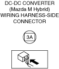
― DC-DC converter (Mazda M Hybrid)
― Integrated starter generator (ISG)
• Are any DTCs displayed?
|
Yes
|
Repair the malfunctioning location according to the applicable DTC troubleshooting.
|
|
No
|
Go to the next step.
|
|
5
|
VERIFY CURRENT INPUT SIGNAL STATUS
-
Warning
-
• While performing this step, always operate the vehicle in a safe and lawful manner.
• When the M-MDS is used to observe monitor system status while driving, be sure to have another technician with you, or record the data in the M-MDS using the PID/DATA MONITOR AND RECORD capturing function and inspect later.
• Access the following PIDs using the M-MDS:
-
― APP1
― APP2
― ECT
― ECT_VOLT
― ECT2
― ECT2_VOLT
― MAF
― MAP
― MAP_VOLT
― A/F_SEN_CUR
― HO2S_OUT_VOLT
― SHRT_FUEL_TRIM
― LONG_FUEL_TRIM
• Do the PIDs indicate the correct values under the malfunction condition?
|
Yes
|
Go to the next step.
|
|
No
|
APP1, APP2 PIDs are not as specified:
• Inspect the APP sensor No.1 and No.2.
ECT, ECT_VOLT, ECT2, ECT2_VOLT PIDs are not as specified:
• Inspect the ECT sensor No.1 and No.2.
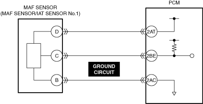
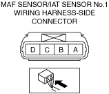
MAF PID is not as specified:
• Inspect the MAF sensor.
MAP, MAP_VOLT PIDs are not as specified:
• Inspect the MAP sensor.
A/F_SEN_CUR, SHRT_FUEL_TRIM, LONG_FUEL_TRIM PIDs are not as specified:
• Inspect the A/F sensor.
HO2S_OUT_VOLT PID is not as specified:
Repair or replace the malfunctioning location.
• If the malfunction remains:
-
― Perform the “Action for Non-repeatable Malfunction” procedure.
|
|
6
|
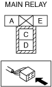
INSPECT MAIN RELAY POWER SUPPLY CIRCUIT FOR SHORT TO GROUND AND OPEN CIRCUIT
• Inspect the power supply circuit for an open circuit and short to ground.
• Is the circuit normal?
|
Yes
|
Go to the next step.
|
|
No
|
Repair or replace the malfunctioning location and perform the repair completion verification.
|
|
7
|
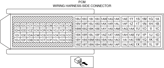
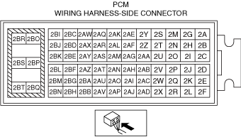
INSPECT PCM CONNECTOR FOR MALFUNCTION
• Inspect the applicable connector and terminal.
• Are the connector and terminal normal?
|
Yes
|
Go to the next step.
|
|
No
|
Repair or replace the malfunctioning location and perform the repair completion verification.
|
|
8
|
INSPECT PCM POWER SUPPLY CIRCUIT FOR SHORT TO GROUND
• Inspect the applicable circuit for a short to ground.
• Is the circuit normal?
|
Yes
|
Go to the next step.
|
|
No
|
Repair or replace the malfunctioning location and perform the repair completion verification.
|
|
9
|
INSPECT MAIN RELAY CONTROL CIRCUIT FOR SHORT TO GROUND
• Inspect the applicable circuit for a short to ground.
• Is the circuit normal?
|
Yes
|
Go to the next step.
|
|
No
|
Repair or replace the malfunctioning location and perform the repair completion verification.
|
|
10
|
INSPECT PCM POWER SUPPLY CIRCUIT FOR OPEN CIRCUIT
• Inspect the applicable circuit for open circuit.
• Is the circuit normal?
|
Yes
|
Go to the next step.
|
|
No
|
Repair or replace the malfunctioning location and perform the repair completion verification.
|
|
11
|
INSPECT MAIN RELAY CONTROL CIRCUIT FOR OPEN CIRCUIT
• Inspect the applicable circuit for open circuit.
• Is the circuit normal?
|
Yes
|
Go to the next step.
|
|
No
|
Repair or replace the malfunctioning location and perform the repair completion verification.
|
|
12
|
INSPECT A/C CUT-OFF CONTROL SYSTEM OPERATION
• Perform the A/C Cut-off Control System Inspection.
• Does the A/C cut-off operation work properly?
|
Yes
|
Go to the next step.
|
|
No
|
Repair or replace the malfunctioning location and perform the repair completion verification.
|
|
13
|
DETERMINE IF MALFUNCTION CAUSE IS DRIVE-BY-WIRE CONTROL SYSTEM OR OTHER
• Will the engine run smoothly at part throttle?
|
Yes
|
Go to Step 15.
|
|
No
|
Go to the next step.
|
|
14
|
INSPECT DRIVE-BY-WIRE CONTROL SYSTEM OPERATION
• Perform the Electronic Control Throttle Operation Inspection.
• Does the drive-by-wire control system work properly?
|
Yes
|
Visually inspect the throttle body (damage/scratching).
• If there is any malfunction:
-
― Repair or replace the malfunctioning location and perform the repair completion verification.
• If there is no malfunction:
-
― Go to the next step.
|
|
No
|
Repair or replace the malfunctioning location and perform the repair completion verification.
|
|
15
|
INSPECT PURGE CONTROL SYSTEM OPERATION
• Perform the Purge Control System Inspection.
• Does the purge solenoid valve work properly?
|
Yes
|
Go to the next step.
|
|
No
|
Repair or replace the malfunctioning location and perform the repair completion verification.
|
|
16
|
INSPECT MAF SENSOR GROUND CIRCUIT FOR OPEN CIRCUIT
• Inspect the applicable circuit for open circuit.
• Is the circuit normal?
|
Yes
|
Go to the next step.
|
|
No
|
Repair or replace the malfunctioning location and perform the repair completion verification.
|
|
17
|
INSPECT PCM FOR POOR GROUND
• Verify the PCM ground point condition.
• Is there any ground point loose or lifting in the PCM?
|
Yes
|
Repair or replace the malfunctioning location and perform the repair completion verification.
|
|
No
|
Go to the next step.
|
|
18
|
INSPECT RELATED PART CONDITION
• Inspect the following:
-
― Fuel quality (proper octane, contamination, winter/summer blend)
― Intake-air system leakage or restriction
― Electrical connectors connection
― Fuel leakage
― Vacuum leakage
― CKP sensor, intake CMP sensor and exhaust CMP sensor
-
• Damaged trigger wheel, intake camshaft and exhaust camshaft
• Is there any malfunction?
|
Yes
|
Repair or replace the malfunctioning location and perform the repair completion verification.
|
|
No
|
Go to the next step.
|
|
19
|
INSPECT FUEL PRESSURE (HIGH-SIDE)
• Start the engine and warm it up completely.
• Access the FUEL_PRES PID using the M-MDS at idle.
• Is the FUEL_PRES PID value within specification?
Specification:
• Approx. 40—60 MPa {408—611 kgf/cm2, 5,802—8,702 psi}
|
Yes
|
Go to Step 23.
|
|
No
|
FUEL_PRES PID value is lower than 40 MPa {408 kgf/cm2, 5,802 psi}:
• Inspect the following:
-
― Fuel leakage at the fuel line and fuel injector
― Fuel pump
-
• Perform the Fuel Pump (Low-pressure Side) Operation Inspection.
― High fuel pressure sensor
― High pressure fuel pump
• If there is any malfunction:
-
― Repair or replace the malfunctioning location and perform the repair completion verification.
• If there is no malfunction:
-
― Go to Step 22.
FUEL_PRES PID value is higher than 60 MPa {611 kgf/cm2, 8,702 psi}:
• Go to the next step.
|
|
20
|
DETERMINE IF MALFUNCTION CAUSE IS HIGH FUEL PRESSURE SENSOR OR HIGH PRESSURE FUEL PUMP
• Is the vehicle acceleration performance normal?
|
Yes
|
Go to the next step.
|
|
No
|
Go to Step 22.
|
|
21
|
INSPECT HIGH FUEL PRESSURE SENSOR FOR MALFUNCTION
• Inspect the applicable part.
• Is the part normal?
|
Yes
|
Go to Step 23.
|
|
No
|
Replace the fuel distributor and perform the repair completion verification.
|
|
22
|
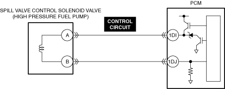
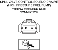
INSPECT SPILL VALVE CONTROL SOLENOID VALVE CONTROL CIRCUIT FOR SHORT TO GROUND
• Inspect the applicable circuit for a short to ground.
• Is the circuit normal?
|
Yes
|
Replace the high pressure fuel pump and perform the repair completion verification.
|
|
No
|
Repair or replace the malfunctioning location and perform the repair completion verification.
|
|
23
|
INSPECT FUEL PRESSURE (LOW-SIDE)
• Connect the fuel pressure gauge between fuel pump and high pressure fuel pump.
• Measure the low side fuel pressure.
• Is the low side fuel pressure within specification?
Specification:
• 545—695 kPa {5.56—7.08 kgf/cm2, 79.1—100.0 psi}
|
Yes
|
Go to the next step.
|
|
No
|
Inspect the following:
• Fuel line restriction
• Fuel filter clogged
-
― If there is any malfunction:
-
• Repair or replace the malfunctioning location and perform the repair completion verification.
― If there is no malfunction:
-
• Replace the fuel pump unit and perform the repair completion verification.
|
|
24
|
INSPECT FUEL INJECTOR OPERATION
• Perform the Fuel Injector Operation Inspection.
• Do the fuel injectors operate properly?
|
Yes
|
Go to the next step.
|
|
No
|
Repair or replace the malfunctioning location and perform the repair completion verification.
|
|
25
|
INSPECT ENGINE COMPRESSION
• Measure the compression pressure for each cylinder.
• Are compression pressures within specification?
|
Yes
|
Go to Step 32.
|
|
No
|
Go to the next step.
|
|
26
|
INSPECT INTAKE ELECTRIC VARIABLE VALVE TIMING DRIVER OR EXHAUST ELECTRIC VARIABLE VALVE TIMING DRIVER FOR MALFUNCTION
• Inspect the applicable part.
• Is the part normal?
|
Yes
|
Go to the next step.
|
|
No
|
Repair or replace the malfunctioning location and perform the repair completion verification.
|
|
27
|
INSPECT INTAKE ELECTRIC VARIABLE VALVE TIMING MOTOR OR EXHAUST ELECTRIC VARIABLE VALVE TIMING MOTOR FOR MALFUNCTION
• Inspect the applicable part.
• Is the part normal?
|
Yes
|
Go to the next step.
|
|
No
|
Repair or replace the malfunctioning location and perform the repair completion verification.
|
|
28
|
INSPECT INTAKE ELECTRIC VARIABLE VALVE TIMING ACTUATOR OR EXHAUST ELECTRIC VARIABLE VALVE TIMING ACTUATOR FOR MALFUNCTION
• Inspect the applicable part.
• Is the part normal?
|
Yes
|
Go to the next step.
|
|
No
|
Repair or replace the malfunctioning location and perform the repair completion verification.
|
|
29
|
INSPECT FOR MALFUNCTION DUE TO DEVIATED VALVE TIMING
• Inspect the valve timing (timing chain installation condition).
• Is the valve timing normal?
|
Yes
|
Inspect for the following engine internal parts:
• Cylinder
• Piston ring
• Intake valve
• Exhaust valve
• Such as cylinder head gasket
-
― If there is any malfunction:
-
• Repair or replace the malfunctioning location and perform the repair completion verification.
|
|
No
|
Adjust the valve timing to the correct timing and perform the repair completion verification.
|
|
30
|
INSPECT IGNITION SYSTEM OPERATION
• Perform the Spark Test.
• Is a strong blue spark visible at each cylinder?
|
Yes
|
Go to the next step.
|
|
No
|
Repair or replace the malfunctioning location and perform the repair completion verification.
|
|
31
|
INSPECT EXHAUST SYSTEM FOR RESTRICTION
• Inspect for restriction in the exhaust system and the catalytic converter.
• Is there any restriction?
|
Yes
|
Repair or replace the malfunctioning location and perform the repair completion verification.
|
|
No
|
Go to the next step.
|
|
32
|
INSPECT IF MALFUNCTION CAUSE IS PCV VALVE OR INJECTOR DRIVER (PCM INTEGRATED)
• Is there any malfunction?
|
Yes
|
Replace the PCV valve and perform the repair completion verification.
|
|
No
|
Injector driver malfunction.
If the problem remains, overhaul the engine and perform the repair completion verification.
|
|
Repair completion verification 1
|
VERIFY THAT VEHICLE IS REPAIRED
• Install/connect the part removed/disconnected during the troubleshooting procedure.
• Has the malfunction symptom been eliminated?
|
Yes
|
Complete the symptom troubleshooting. (Explain contents of repair to customer)
|
|
No
|
Refer to the controller area network (CAN) malfunction diagnosis flow to inspect for a CAN communication error.
• If the CAN communication is normal, perform the diagnosis from Step 1.
-
― If the malfunction recurs, go to the next step.
|
|
Repair completion verification 2
|
VERIFY IF MALFUNCTION IS CAUSED BY NOT PERFORMING PCM REPROGRAMMING
• Verify repair information and verify that there is a new calibration in the PCM.
• Is there a new calibration in the PCM?
|
Yes
|
Perform the PCM reprogramming and verify if the malfunction symptom was corrected.
• If the malfunction recurs, replace the PCM.
|
|
No
|
Replace the PCM.
|