|
1
|
VERIFY IF MALFUNCTION INCLUDES HARD ENGINE STARTING
• Is the engine unable to start after it has stalled?
-
Note
-
• If the ignition is not switched off or ACC after the engine stalls, and then an engine restart is attempted, the PCM corrects the difference between CKP sensor and CMP sensor signals caused by engine stalling, which may result in more time needed to restart the engine.
|
Yes
|
If the engine is unable to start, perform the symptom troubleshooting “WILL NOT CRANK” and “CRANKS NORMALLY BUT WILL NOT START”.
|
|
No
|
Go to the next step.
|
|
2
|
VERIFY IF MALFUNCTION INCLUDES ROUGH IDLING
• Does the engine idle rough?
|
Yes
|
Perform the symptom troubleshooting “ENGINE RUNS ROUGH/ROLLING IDLE”.
|
|
No
|
Go to the next step.
|
|
3
|
VERIFY PCM DTC
• Perform the DTC inspection for the PCM.
• Are any DTCs displayed?
|
Yes
|
Repair the malfunctioning location according to the applicable DTC troubleshooting.
|
|
No
|
Go to the next step.
|
|
4
|
VERIFY CURRENT INPUT SIGNAL STATUS
-
Warning
-
• While performing this step, always operate the vehicle in a safe and lawful manner.
• When the M-MDS is used to observe monitor system status while driving, be sure to have another technician with you, or record the data in the M-MDS using the PID/DATA MONITOR AND RECORD capturing function and inspect later.
• Access the following PIDs using the M-MDS:
PCM:
-
― APP1
― APP2
― CLTCH_PEDAL_POS (MTX)
― ECT
― ECT_VOLT
― ECT2
― ECT2_VOLT
― MAF
― MAP
― MAP_VOLT
― TP_RELAT
― A/F_SEN_CUR
― HO2S_OUT_VOLT
― SHRT_FUEL_TRIM
― LONG_FUEL_TRIM
Electrical supply unit (ESU):
-
― BRK_SW
• Do the PIDs indicate the correct values under the malfunction condition?
|
Yes
|
Go to the next step.
|
|
No
|
APP1, APP2 PIDs are not as specified:
• Inspect the APP sensor No.1 and No.2.
CLTCH_PEDAL_POS PID is not as specified: (MTX)
• Inspect the clutch stroke sensor.
ECT, ECT_VOLT, ECT2, ECT2_VOLT PIDs are not as specified:
• Inspect the ECT sensor No.1 and No.2.
MAF PID is not as specified:
• Inspect the MAF sensor.
MAP, MAP_VOLT PIDs are not as specified:
• Inspect the MAP sensor.
TP_RELAT PID is not as specified:
A/F_SEN_CUR, SHRT_FUEL_TRIM, LONG_FUEL_TRIM PIDs are not as specified:
• Inspect the A/F sensor.
HO2S_OUT_VOLT PID is not as specified:
BRK_SW PID is not as specified:
• Inspect the brake switch.
Repair or replace the malfunctioning location.
• If the malfunction remains:
-
― Inspect communication error between TCM and PCM. (ATX)
-
• Repair or replace the malfunctioning location and perform the repair completion verification.
― Perform the “Action for Non-repeatable Malfunction” procedure.
|
|
5
|
DETERMINE IF MALFUNCTION CAUSE IS A/C REQUEST SIGNAL OR OTHER
• Access the PCM PID A/C_REQ using the M-MDS.
• Monitor the A/C_REQ PID while turning on and off the air conditioner using the switch on the control panel.
• Does the A/C_REQ PID value change from on to off according to switch control panel?
|
Yes
|
Go to the next step.
|
|
No
|
If the A/C_REQ PID is always ON:
• Perform the symptom troubleshooting “A/C IS ALWAYS ON OR A/C COMPRESSOR RUNS CONTINUOUSLY”.
If the A/C_REQ PID is always OFF:
• Perform the symptom troubleshooting “A/C DOES NOT WORK SUFFICIENTLY”.
|
|
6
|
DETERMINE IF MALFUNCTION CAUSE IS DRIVE-BY-WIRE CONTROL SYSTEM OR OTHER
• Will the engine run smoothly at part throttle?
|
Yes
|
Go to Step 8.
|
|
No
|
Go to the next step.
|
|
7
|
INSPECT DRIVE-BY-WIRE CONTROL SYSTEM OPERATION
• Perform the Electronic Control Throttle Operation Inspection.
• Does the drive-by-wire control system work properly?
|
Yes
|
Visually inspect the throttle body (damage/scratching).
• If there is any malfunction:
-
― Repair or replace the malfunctioning location and perform the repair completion verification.
• If there is no malfunction:
-
― Go to the next step.
|
|
No
|
Repair or replace the malfunctioning location and perform the repair completion verification.
|
|
8
|
INSPECT FUEL INJECTOR OPERATION
• Perform the Fuel Injector Operation Inspection.
• Do the fuel injectors operate properly?
|
Yes
|
Go to the next step.
|
|
No
|
Repair or replace the malfunctioning location and perform the repair completion verification.
|
|
9
|
INSPECT PURGE CONTROL SYSTEM OPERATION
• Perform the Purge Control System Inspection.
• Does the purge solenoid valve work properly?
|
Yes
|
Go to the next step.
|
|
No
|
Repair or replace the malfunctioning location and perform the repair completion verification.
|
|
10
|
INSPECT RELATED PART CONDITION
• Inspect the following:
-
― Fuel quality (proper octane, contamination, winter/summer blend)
― Intake-air system restriction or leakage
― Fuel leakage in fuel system
― Vacuum leakage
― Engine mount loose
― CKP sensor, intake CMP sensor and exhaust CMP sensor
-
• Damaged trigger wheel, intake camshaft and exhaust camshaft
• Is there any malfunction?
|
Yes
|
Repair or replace the malfunctioning location and perform the repair completion verification.
|
|
No
|
Go to the next step.
|
|
11
|
INSPECT FUEL PRESSURE (HIGH-SIDE)
• Start the engine and warm it up completely.
• Access the PCM PID FUEL_PRES using the M-MDS at idle.
• Is the FUEL_PRES PID value within specification?
Specification:
• Approx. 40—60 MPa {408—611 kgf/cm2, 5,802—8,702 psi}
|
Yes
|
Go to Step 15.
|
|
No
|
FUEL_PRES PID value is lower than 40 MPa {408 kgf/cm2, 5,802 psi}:
• Inspect the following:
-
― Fuel leakage at the fuel line and fuel injector
― Fuel pump
-
• Perform the Fuel Pump (Low-pressure Side) Operation Inspection.
― High fuel pressure sensor
― High pressure fuel pump
• If there is any malfunction:
-
― Repair or replace the malfunctioning location and perform the repair completion verification.
• If there is no malfunction:
-
― Go to Step 14.
FUEL_PRES PID value is higher than 60 MPa {611 kgf/cm2, 8,702 psi}:
• Go to the next step.
|
|
12
|
DETERMINE IF MALFUNCTION CAUSE IS HIGH FUEL PRESSURE SENSOR OR HIGH PRESSURE FUEL PUMP
• Is the vehicle acceleration performance normal?
|
Yes
|
Go to the next step.
|
|
No
|
Go to Step 14.
|
|
13
|
INSPECT HIGH FUEL PRESSURE SENSOR FOR MALFUNCTION
• Inspect the applicable part.
• Is the part normal?
|
Yes
|
Go to Step 15.
|
|
No
|
Replace the fuel distributor and perform the repair completion verification.
|
|
14
|
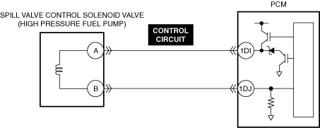
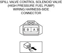
INSPECT SPILL VALVE CONTROL SOLENOID VALVE CONTROL CIRCUIT FOR SHORT TO GROUND
• Inspect the applicable circuit for a short to ground.
• Is the circuit normal?
|
Yes
|
Replace the high pressure fuel pump and perform the repair completion verification.
|
|
No
|
Repair or replace the malfunctioning location and perform the repair completion verification.
|
|
15
|
INSPECT FUEL PRESSURE (LOW-SIDE)
• Connect the fuel pressure gauge between fuel pump and high pressure fuel pump.
• Measure the low side fuel pressure.
• Is the low side fuel pressure within specification?
Specification:
• 545—695 kPa {5.56—7.08 kgf/cm2, 79.1—100.0 psi}
|
Yes
|
Go to the next step.
|
|
No
|
Inspect the following:
• Fuel line restriction
• Fuel filter clogged
-
― If there is any malfunction:
-
• Repair or replace the malfunctioning location and perform the repair completion verification.
― If there is no malfunction:
-
• Replace the fuel pump unit and perform the repair completion verification.
|
|
16
|
INSPECT ENGINE COMPRESSION
• Measure the compression pressure for each cylinder.
• Are compression pressures within specification?
|
Yes
|
Go to Step 21.
|
|
No
|
Go to the next step.
|
|
17
|
INSPECT INTAKE ELECTRIC VARIABLE VALVE TIMING DRIVER OR EXHAUST ELECTRIC VARIABLE VALVE TIMING DRIVER FOR MALFUNCTION
• Inspect the applicable part.
• Is the part normal?
|
Yes
|
Go to the next step.
|
|
No
|
Repair or replace the malfunctioning location and perform the repair completion verification.
|
|
18
|
INSPECT INTAKE ELECTRIC VARIABLE VALVE TIMING MOTOR OR EXHAUST ELECTRIC VARIABLE VALVE TIMING MOTOR FOR MALFUNCTION
• Inspect the applicable part.
• Is the part normal?
|
Yes
|
Go to the next step.
|
|
No
|
Repair or replace the malfunctioning location and perform the repair completion verification.
|
|
19
|
INSPECT INTAKE ELECTRIC VARIABLE VALVE TIMING ACTUATOR OR EXHAUST ELECTRIC VARIABLE VALVE TIMING ACTUATOR FOR MALFUNCTION
• Inspect the applicable part.
• Is the part normal?
|
Yes
|
Go to the next step.
|
|
No
|
Repair or replace the malfunctioning location and perform the repair completion verification.
|
|
20
|
INSPECT FOR MALFUNCTION DUE TO DEVIATED VALVE TIMING
• Inspect the valve timing (timing chain installation condition).
• Is the valve timing normal?
|
Yes
|
Inspect for the following engine internal parts:
• Cylinder
• Piston ring
• Intake valve
• Exhaust valve
• Such as cylinder head gasket
-
― If there is any malfunction:
-
• Repair or replace the malfunctioning location and perform the repair completion verification.
|
|
No
|
Adjust the valve timing to the correct timing and perform the repair completion verification.
|
|
21
|
INSPECT ENGINE MOUNT FOR LOOSENESS
• Inspect the engine mount for looseness.
• Is the engine mount normal?
|
Yes
|
ATX:
• Go to the next step.
MTX:
• Go to Step 24.
|
|
No
|
Repair or replace the malfunctioning location and perform the repair completion verification.
|
|
22
|
VERIFY TCM DTC
• Perform the DTC inspection for the TCM.
• Are any DTCs displayed?
|
Yes
|
Repair the malfunctioning location according to the applicable DTC troubleshooting.
|
|
No
|
Go to the next step.
|
|
23
|
VERIFY INTEGRATED STARTER GENERATOR (ISG) DTCs
• Perform the DTC inspection for the integrated starter generator (ISG).
• Are any DTCs displayed?
|
Yes
|
Repair the malfunctioning location according to the applicable DTC troubleshooting.
|
|
No
|
Injector driver malfunction.
If the problem remains, overhaul the engine and perform the repair completion verification.
|
|
Repair completion verification 1
|
VERIFY THAT VEHICLE IS REPAIRED
• Install/connect the part removed/disconnected during the troubleshooting procedure.
• Has the malfunction symptom been eliminated?
|
Yes
|
Complete the symptom troubleshooting. (Explain contents of repair to customer)
|
|
No
|
Refer to the controller area network (CAN) malfunction diagnosis flow to inspect for a CAN communication error.
• If the CAN communication is normal, perform the diagnosis from Step 1.
-
― If the malfunction recurs, go to the next step.
|
|
Repair completion verification 2
|
VERIFY IF MALFUNCTION IS CAUSED BY NOT PERFORMING PCM REPROGRAMMING
• Verify repair information and verify that there is a new calibration in the PCM.
• Is there a new calibration in the PCM?
|
Yes
|
Perform the PCM reprogramming and verify if the malfunction symptom was corrected.
• If the malfunction recurs, replace the PCM.
|
|
No
|
Replace the PCM.
|