• A hot engine can cause severe burns. Turn off the engine and wait until it is cool before servicing.
• Fuel vapor is hazardous. It can very easily ignite, causing serious injury and damage. Always keep sparks and flames away from fuel.
• When removing/installing the engine, verify that the engine and transaxle are securely supported. Otherwise, the engine may fall off and cause serious injury or death, and damage to the vehicle.
• Highly pressurized fuel may spray out if the fuel line is cut. Due to the following dangers occurring with a fuel spray, always complete the “Fuel Line Safety Procedure” to prevent the fuel from spraying.
― Fuel may cause irritation if it comes in contact with skin and eyes.
― If fuel ignites and causes a fire, it may lead to serious injury or death, and damage to property and facilities.
Caution
• If the intake-air system, exhaust system, or the engine is damaged, fragments of the damaged part may be remaining in the intake-air system or exhaust system. If the engine is replaced without removing fragments of the damaged part, it could cause engine damage or malfunction. Before replacing the engine, verify that no fragments remain in the parts to be reused.
• Secure the steering wheel using tape or a cable to prevent the steering shaft from rotating after disconnecting the steering shaft. If the steering wheel rotates after the steering shaft and the steering gear and linkage are disconnected, the internal parts of the clock spring could be damaged.
• Applying excessive force (force of 100 N {10.2 kgf, 22.5 lbf} or more) to the electric variable valve timing motor/driver may cause a malfunction. When servicing, be careful not to apply excessive force to the electric variable valve timing motor/driver using other parts or tools.
Note
• Perform the engine and transaxle component removal/installation from below the vehicle.
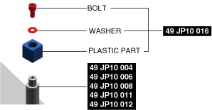
1. Install the plastic part of SST (49 JP10 016) to the tip of SST (49 JP10 004 / 49 JP10 006 / 49 JP10 008 / 49 JP10 011 / 49 JP10 012), and secure it with the included bolt and washer.
am3zzw00037016
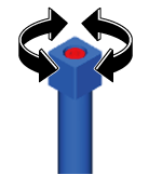
Note
• The plastic part can be rotated freely even after being secured with the included bolt and washer.
a59cjw00002119
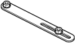
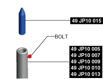
2. Insert SST (49 JP10 015) into the tip of SST (49 JP10 005 / 49 JP10 007 / 49 JP10 009 / 49 JP10 010 / 49 JP10 013), and secure it with the included bolt.
am3zzw00037017
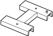
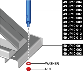
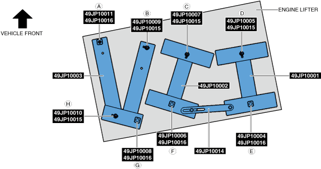
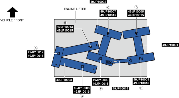
3. Secure the SST shown in the figure using the included nut and washer.
am3zzw00037018
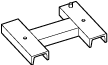
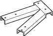
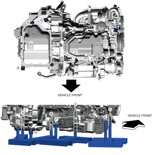
4. Position the SSTs assembled in Step 3 to the engine lifter as shown in the figure.
ATX
am3zzw00037019
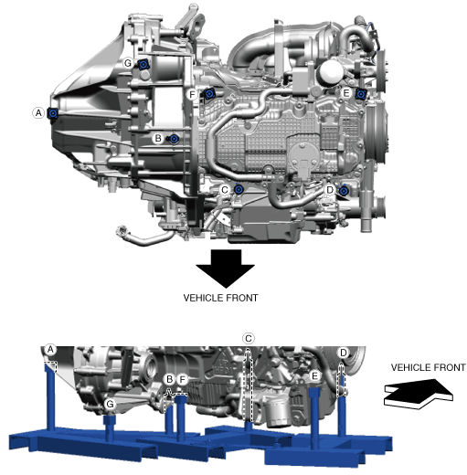
MTX
am3zzw00037020
5. Set the SSTs positioned in Step 4 to the engine and transaxle.
ATX
am3zzw00037021
MTX
am3zzw00037022
6. Verify that the engine and transaxle are securely held by the SSTs, then remove the engine and transaxle from the vehicle.
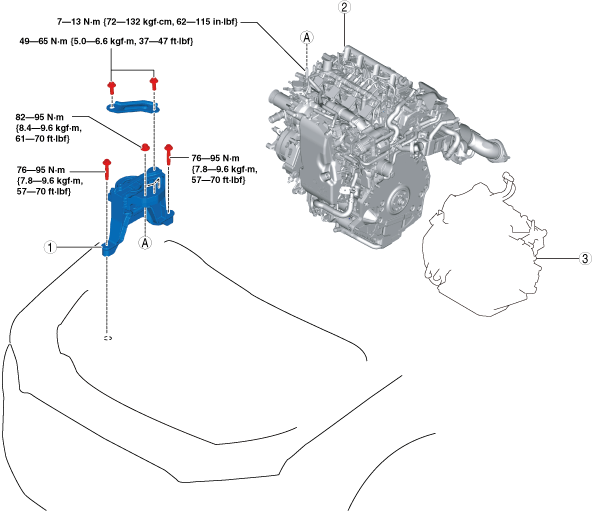
No.3 engine mount installation note
1. Temporarily tighten the No.3 engine mount installation bolts and nuts using the following procedure:
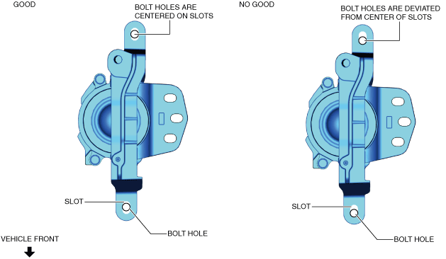
(1) Temporarily tighten the bolts shown in the figure so that they are centered on the No.3 engine mount slots.
am30jw00000599
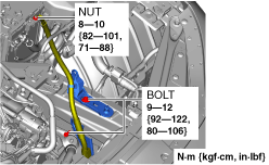
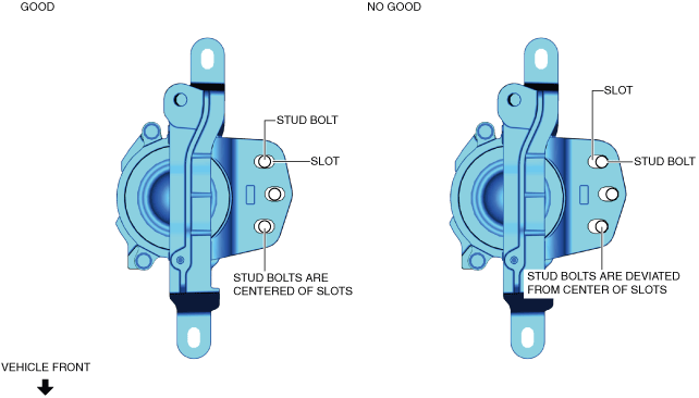
(2) Temporarily tighten the nuts shown in the figure so that the stud bolts of the engine front cover are centered on the No.3 engine mount slots.
• If the stud bolts are deviated from the center of the slots, align the stud bolts with the center of the slots while slightly moving the engine, and temporarily tighten the installation nuts.
am30jw00000600
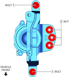
2. Tighten the No.3 engine mount installation bolts and nuts in the order shown in the figure.