Home REAR WASHER HOSE REMOVAL/INSTALLATION [(E)]
id0919008016x2
Replacement Part
Inner liftgate grommet
Quantity: 2
Location of use: Liftgate
Warning
Note
• If the procedure is performed with washer fluid in the washer tank, the washer fluid may leak out. When performing the procedure, place a container under the washer tank to collect washer fluid, and perform the procedure.
1. Disconnect the negative battery terminal. (See NEGATIVE BATTERY TERMINAL DISCONNECTION/CONNECTION [(E)]
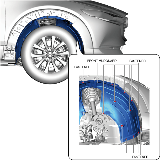
2. Remove the front over fender (RH). (See FRONT OVER FENDER REMOVAL/INSTALLATION
3. Remove the fasteners.
4. Set the front mudguard (RH) aside.
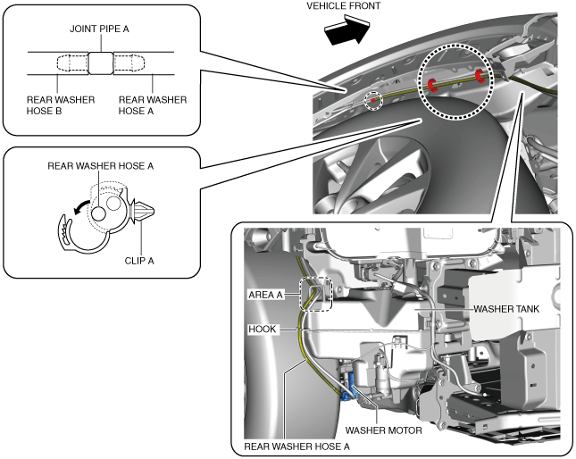
5. Disconnect the rear washer hose A from the washer motor.
6. Remove the rear washer hose A from the washer tank hook. (See Rear washer hose A installation note
7. Pull out the windshield washer hose A from area A of the washer tank.
8. Remove the rear washer hose A from clips A.
9. Disconnect the rear washer hose A from the joint pipe A and remove it.
10. Install in the reverse order of removal.
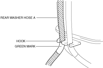
• When installing rear washer hose A to the washer tank hook, align the hook with the upper part of the green mark and install.
1. Disconnect the negative battery terminal and wait for 1 min or more . (See NEGATIVE BATTERY TERMINAL DISCONNECTION/CONNECTION [(E)]
2. Remove the front over fender (RH). (See FRONT OVER FENDER REMOVAL/INSTALLATION
3. Remove the fasteners.
4. Set the front mudguard(RH) aside.
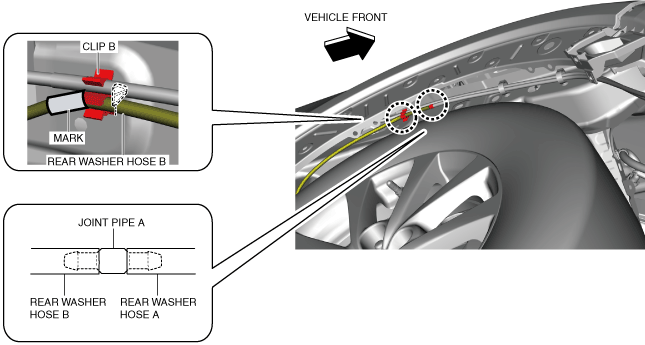
5. Disconnect the rear washer hose B from the joint pipe A.
6. Remove the rear washer hose B from the clip B.
7. Remove the following parts:
(1) A-pillar trim (See A-PILLAR TRIM REMOVAL/INSTALLATION [(E)]
(2) Front scuff plate (See FRONT SCUFF PLATE REMOVAL/INSTALLATION
(3) Front side trim (See FRONT SIDE TRIM REMOVAL/INSTALLATION
(4) Passenger-side decoration panel (See DECORATION PANEL REMOVAL/INSTALLATION
(5) Glove compartment (See GLOVE COMPARTMENT REMOVAL/INSTALLATION
(6) Dashboard under cover (See DASHBOARD UNDER COVER REMOVAL/INSTALLATION
(7) Passenger-side lower panel (See LOWER PANEL REMOVAL/INSTALLATION [(E)]
(8) Driver-side decoration panel (See DECORATION PANEL REMOVAL/INSTALLATION
(9) Shift lever knob (MTX) (See SHIFT LEVER REMOVAL/INSTALLATION [C66M-R, C66MX-R]
(10) Selector lever knob (ATX) (See SELECTOR LEVER COMPONENT REMOVAL/INSTALLATION
(11) Upper panel (See UPPER PANEL REMOVAL/INSTALLATION
(12) Console side panel (See CONSOLE SIDE PANEL REMOVAL/INSTALLATION
(13) Shift panel (See SHIFT PANEL REMOVAL/INSTALLATION
(14) Front console box (See FRONT CONSOLE BOX REMOVAL/INSTALLATION
(15) Cup holder (See CUP HOLDER REMOVAL/INSTALLATION
(16) Side wall (See SIDE WALL REMOVAL/INSTALLATION
(17) Rear console (See REAR CONSOLE REMOVAL/INSTALLATION [(E)]
(18) Driver-side lower panel (See LOWER PANEL REMOVAL/INSTALLATION [(E)]
(19) Driver-side knee air bag module (See KNEE AIR BAG MODULE REMOVAL/INSTALLATION [STANDARD DEPLOYMENT CONTROL SYSTEM] KNEE AIR BAG MODULE REMOVAL/INSTALLATION [TWO-STEP DEPLOYMENT CONTROL SYSTEM]
(20) Center lower panel (See LOWER PANEL REMOVAL/INSTALLATION [(E)]
(21) Driver-side air bag module (See DRIVER-SIDE AIR BAG MODULE REMOVAL [STANDARD DEPLOYMENT CONTROL SYSTEM] DRIVER-SIDE AIR BAG MODULE INSTALLATION [STANDARD DEPLOYMENT CONTROL SYSTEM] DRIVER-SIDE AIR BAG MODULE REMOVAL [TWO-STEP DEPLOYMENT CONTROL SYSTEM] DRIVER-SIDE AIR BAG MODULE INSTALLATION [TWO-STEP DEPLOYMENT CONTROL SYSTEM]
(22) Steering wheel (See STEERING WHEEL AND COLUMN REMOVAL/INSTALLATION [(E)]
(23) Upper column cover (See COLUMN COVER REMOVAL/INSTALLATION
(24) Lower column cover (See COLUMN COVER REMOVAL/INSTALLATION
(25) Clock spring (See CLOCK SPRING REMOVAL/INSTALLATION [STANDARD DEPLOYMENT CONTROL SYSTEM] CLOCK SPRING REMOVAL/INSTALLATION [TWO-STEP DEPLOYMENT CONTROL SYSTEM]
(26) Light switch (See LIGHT SWITCH REMOVAL/INSTALLATION [(E)]
(27) Wiper and washer switch (See WIPER AND WASHER SWITCH REMOVAL/INSTALLATION [(E)]
(28) Joint cover (See STEERING WHEEL AND COLUMN REMOVAL/INSTALLATION [(E)]
(29) Steering column component (See STEERING WHEEL AND COLUMN REMOVAL/INSTALLATION [(E)]
(30) Instrument cluster (See INSTRUMENT CLUSTER REMOVAL/INSTALLATION
(31) Center speaker grille (See SPEAKER GRILLE REMOVAL/INSTALLATION
(32) Center display component (See CENTER DISPLAY REMOVAL/INSTALLATION
(33) Connectivity master unit (CMU) (See CONNECTIVITY MASTER UNIT (CMU) REMOVAL/INSTALLATION
(34) Audio panel (with audio panel) (See AUDIO PANEL REMOVAL/INSTALLATION
(35) CD player (with CD player) (See CD PLAYER REMOVAL/INSTALLATION
(36) DVD/CD player (with DVD/CD player) (See DVD/CD PLAYER REMOVAL/INSTALLATION
(37) Climate control unit (See CLIMATE CONTROL UNIT REMOVAL/INSTALLATION [FULL-AUTO AIR CONDITIONER (E)] CLIMATE CONTROL UNIT REMOVAL/INSTALLATION [MANUAL AIR CONDITIONER (E)]
(38) Dashboard side cover (See DASHBOARD SIDE COVER REMOVAL/INSTALLATION
(39) Rear heat duct No.1 (See REAR HEAT DUCT REMOVAL/INSTALLATION [(E)]
(40) Driver-side front heat duct No.2 (See FRONT HEAT DUCT REMOVAL/INSTALLATION [(E)]
(41) Windshield wiper arm and blade (See WINDSHIELD WIPER ARM AND BLADE REMOVAL/INSTALLATION
(42) Cowl grille (See COWL GRILLE REMOVAL/INSTALLATION
(43) Dashboard (See DASHBOARD REMOVAL [(E)] DASHBOARD INSTALLATION [(E)]
(44) Blower unit (L.H.D.) (See BLOWER UNIT REMOVAL/INSTALLATION [(E)]
(45) Passenger-side cowl side woofer (L.H.D.) (See COWL SIDE WOOFER REMOVAL/INSTALLATION [(E)]
(46) Driver-side cowl side woofer (R.H.D.) (See COWL SIDE WOOFER REMOVAL/INSTALLATION [(E)]
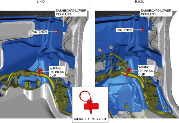
8. Remove the fasteners.
9. Remove the wiring harness clip.
10. Set the dashboard lower insulator aside.
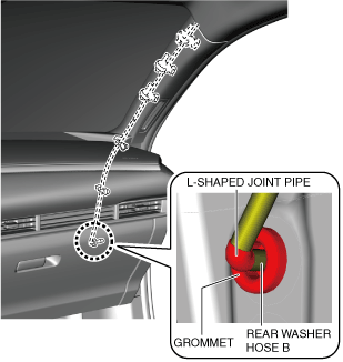
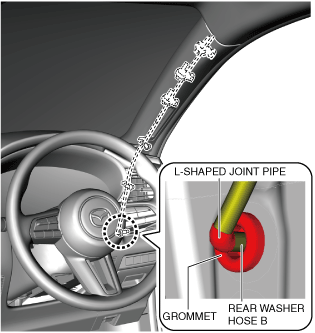
11. Pull out the grommet into the cabin side.
12. Disconnect rear washer hose B from the L-shaped joint pipe.
L.H.D.
R.H.D.
13. Install in the reverse order of removal.
1. Disconnect the negative battery terminal and wait for 1 min or more . (See NEGATIVE BATTERY TERMINAL DISCONNECTION/CONNECTION [(E)]
2. Remove the following parts:
(1) A-pillar trim (See A-PILLAR TRIM REMOVAL/INSTALLATION [(E)]
(2) Front scuff plate (See FRONT SCUFF PLATE REMOVAL/INSTALLATION
(3) Front side trim (See FRONT SIDE TRIM REMOVAL/INSTALLATION
(4) Passenger-side decoration panel (See DECORATION PANEL REMOVAL/INSTALLATION
(5) Glove compartment (See GLOVE COMPARTMENT REMOVAL/INSTALLATION
(6) Dashboard under cover (See DASHBOARD UNDER COVER REMOVAL/INSTALLATION
(7) Passenger-side lower panel (See LOWER PANEL REMOVAL/INSTALLATION [(E)]
(8) Driver-side decoration panel (See DECORATION PANEL REMOVAL/INSTALLATION
(9) Shift lever knob (MTX) (See SHIFT LEVER REMOVAL/INSTALLATION [C66M-R, C66MX-R]
(10) Selector lever knob (ATX) (See SELECTOR LEVER COMPONENT REMOVAL/INSTALLATION
(11) Upper panel (See UPPER PANEL REMOVAL/INSTALLATION
(12) Console side panel (See CONSOLE SIDE PANEL REMOVAL/INSTALLATION
(13) Shift panel (See SHIFT PANEL REMOVAL/INSTALLATION
(14) Front console box (See FRONT CONSOLE BOX REMOVAL/INSTALLATION
(15) Cup holder (See CUP HOLDER REMOVAL/INSTALLATION
(16) Side wall (See SIDE WALL REMOVAL/INSTALLATION
(17) Rear console (See REAR CONSOLE REMOVAL/INSTALLATION [(E)]
(18) Driver-side lower panel (See LOWER PANEL REMOVAL/INSTALLATION [(E)]
(19) Driver-side knee air bag module (See KNEE AIR BAG MODULE REMOVAL/INSTALLATION [STANDARD DEPLOYMENT CONTROL SYSTEM] KNEE AIR BAG MODULE REMOVAL/INSTALLATION [TWO-STEP DEPLOYMENT CONTROL SYSTEM]
(20) Center lower panel (See LOWER PANEL REMOVAL/INSTALLATION [(E)]
(21) Driver-side air bag module (See DRIVER-SIDE AIR BAG MODULE REMOVAL [STANDARD DEPLOYMENT CONTROL SYSTEM] DRIVER-SIDE AIR BAG MODULE INSTALLATION [STANDARD DEPLOYMENT CONTROL SYSTEM] DRIVER-SIDE AIR BAG MODULE REMOVAL [TWO-STEP DEPLOYMENT CONTROL SYSTEM] DRIVER-SIDE AIR BAG MODULE INSTALLATION [TWO-STEP DEPLOYMENT CONTROL SYSTEM]
(22) Steering wheel (See STEERING WHEEL AND COLUMN REMOVAL/INSTALLATION [(E)]
(23) Upper column cover (See COLUMN COVER REMOVAL/INSTALLATION
(24) Lower column cover (See COLUMN COVER REMOVAL/INSTALLATION
(25) Clock spring (See CLOCK SPRING REMOVAL/INSTALLATION [STANDARD DEPLOYMENT CONTROL SYSTEM] CLOCK SPRING REMOVAL/INSTALLATION [TWO-STEP DEPLOYMENT CONTROL SYSTEM]
(26) Light switch (See LIGHT SWITCH REMOVAL/INSTALLATION [(E)]
(27) Wiper and washer switch (See WIPER AND WASHER SWITCH REMOVAL/INSTALLATION [(E)]
(28) Joint cover (See STEERING WHEEL AND COLUMN REMOVAL/INSTALLATION [(E)]
(29) Steering column component (See STEERING WHEEL AND COLUMN REMOVAL/INSTALLATION [(E)]
(30) Instrument cluster (See INSTRUMENT CLUSTER REMOVAL/INSTALLATION
(31) Center speaker grille (See SPEAKER GRILLE REMOVAL/INSTALLATION
(32) Center display component (See CENTER DISPLAY REMOVAL/INSTALLATION
(33) Connectivity master unit (CMU) (See CONNECTIVITY MASTER UNIT (CMU) REMOVAL/INSTALLATION
(34) Audio panel (with audio panel) (See AUDIO PANEL REMOVAL/INSTALLATION
(35) CD player (with CD player) (See CD PLAYER REMOVAL/INSTALLATION
(36) DVD/CD player (with DVD/CD player) (See DVD/CD PLAYER REMOVAL/INSTALLATION
(37) Climate control unit (See CLIMATE CONTROL UNIT REMOVAL/INSTALLATION [FULL-AUTO AIR CONDITIONER (E)] CLIMATE CONTROL UNIT REMOVAL/INSTALLATION [MANUAL AIR CONDITIONER (E)]
(38) Dashboard side cover (See DASHBOARD SIDE COVER REMOVAL/INSTALLATION
(39) Rear heat duct No.1 (See REAR HEAT DUCT REMOVAL/INSTALLATION [(E)]
(40) Driver-side front heat duct No.2 (See FRONT HEAT DUCT REMOVAL/INSTALLATION [(E)]
(41) Windshield wiper arm and blade (See WINDSHIELD WIPER ARM AND BLADE REMOVAL/INSTALLATION
(42) Cowl grille (See COWL GRILLE REMOVAL/INSTALLATION
(43) Dashboard (See DASHBOARD REMOVAL [(E)] DASHBOARD INSTALLATION [(E)]
(44) Blower unit (L.H.D.) (See BLOWER UNIT REMOVAL/INSTALLATION [(E)]
(45) Passenger-side cowl side woofer (L.H.D.) (See COWL SIDE WOOFER REMOVAL/INSTALLATION [(E)]
(46) Driver-side cowl side woofer (R.H.D.) (See COWL SIDE WOOFER REMOVAL/INSTALLATION [(E)]
3. Remove the fasteners.
4. Remove the wiring harness clip.
5. Set the dashboard lower insulator aside.
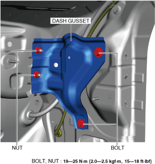
6. Remove the bolts and nuts.
7. Remove the dash gusset.
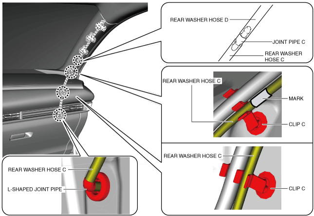
8. Disconnect rear washer hose C from the L-shaped joint pipe.
9. Remove the rear washer hose C from clip C.
L.H.D.
R.H.D.
10. Disconnect the rear washer hose C from the joint pipe C.
11. Install in the reverse order of removal.
1. Disconnect the negative battery terminal and wait for 1 min or more . (See NEGATIVE BATTERY TERMINAL DISCONNECTION/CONNECTION [(E)]
2. Remove the following parts:
(1) A-pillar trim (See A-PILLAR TRIM REMOVAL/INSTALLATION [(E)]
(2) Sunvisor (See SUNVISOR REMOVAL/INSTALLATION
(3) Front map light (See FRONT MAP LIGHT REMOVAL/INSTALLATION [(E)]
(4) Sensor cover (See SENSOR COVER REMOVAL/INSTALLATION
(5) Assist handle (See ASSIST HANDLE REMOVAL/INSTALLATION
(6) Front seat belt lower anchor (See FRONT SEAT BELT REMOVAL/INSTALLATION
(7) B-pillar upper trim (See B-PILLAR UPPER TRIM REMOVAL/INSTALLATION
(8) Rear package tray (See REAR PACKAGE TRAY REMOVAL/INSTALLATION
(9) Trunk side upper trim (See TRUNK SIDE UPPER TRIM REMOVAL/INSTALLATION
(10) C-pillar trim (See C-PILLAR TRIM REMOVAL/INSTALLATION
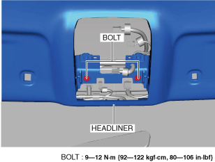
3. Remove the bolts.
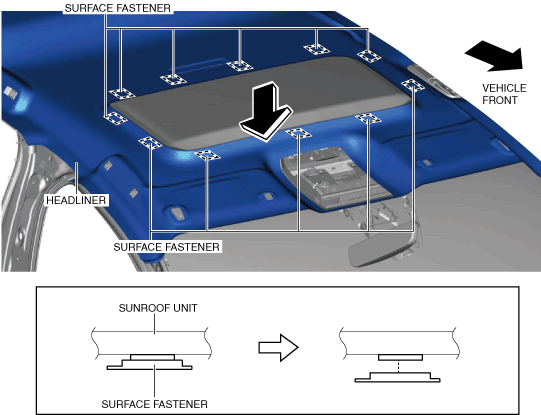
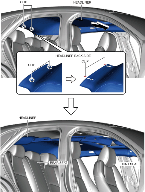
4. Move the headliner in the direction of the arrows shown in the figure and detach the surface fasteners from the sunroof unit. (with sunroof system)
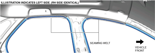
5. Partially peel back the seaming welts.
6. Slide the headliner in the direction of the arrow shown in the figure.
7. Set the headliner on front seats and rear seats.
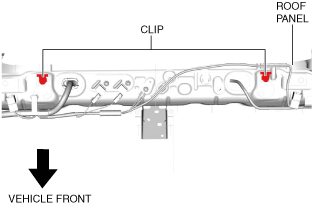
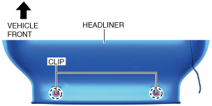
8. Remove the clips from the roof panel.
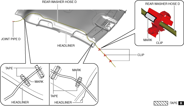
9. Remove the rear washer hose D from the clip.
10. Remove the tape.
11. Disconnect the rear washer hose D from the joint pipe D.
12. Remove the rear washer hose D.
13. Install in the reverse order of removal. (See Headliner Installation Note
Note
• The rear washer hose E is integrated with the antenna feeder No.1.
1. Before installing the headliner, install the clips to the headliner.