 |
a30zzw00002920
AIR BAG MODULE AND PRE-TENSIONER SEAT BELT DEPLOYMENT PROCEDURES [TWO-STEP DEPLOYMENT CONTROL SYSTEM]
id0810b1801100
Preparation Before Servicing
1. Switch the ignition off.
2. Disconnect the negative battery terminal and wait for 1 min or more. (See NEGATIVE BATTERY TERMINAL DISCONNECTION/CONNECTION [(E)].)
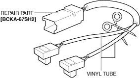
3. Cut the location of the repair part [BCKA-67SH2] as shown in the figure and remove the vinyl tube.
a30zzw00002920
|
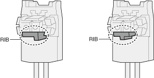
4. Check the rib shape of the connector and select a wiring harness that matches the inflator.
a30zzw00002921
|
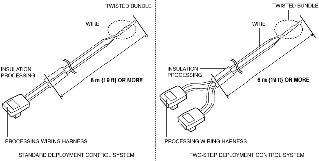
5. Connect the wiring harness selected in Step 4 to a wire that meets all of the following requirements. (See REPAIR CONNECTOR REPLACEMENT/WIRING HARNESS CONNECTION.)
a30zzw00004486
|
6. Before connecting to the inflator, peel off the end coating of the wires and short-circuit them by twisting them to prevent accidental explosion due to static electricity.
7. Activate (deploy) the relevant air bag module or pre-tensioner seat belt.
Activation (Deployment) Inside The Vehicle
Driver-side air bag module
1. Remove the driver-side air bag module. (See DRIVER-SIDE AIR BAG MODULE REMOVAL [TWO-STEP DEPLOYMENT CONTROL SYSTEM].)
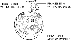
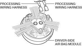
2. Connect the processing wiring harness to the driver-side air bag module.
a30zzw00002923
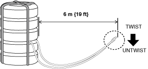
|
3. Install the driver-side air bag module. (See DRIVER-SIDE AIR BAG MODULE INSTALLATION [TWO-STEP DEPLOYMENT CONTROL SYSTEM].)
4. Verify that all persons are standing at least 6 m {19 ft} away from the vehicle.
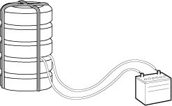
5. Untwist the processing wiring harness.
6. Connect the processing wiring harness to the lead-acid battery and activate the inflator.
Passenger-side air bag module
1. Remove the glove compartment. (See GLOVE COMPARTMENT REMOVAL/INSTALLATION.)
a30zzw00002924
|
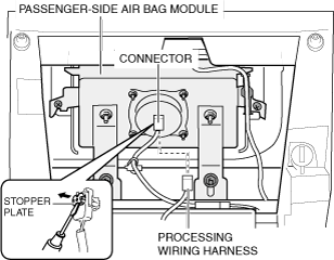
2. Pull out the connector stopper plate using a flathead screwdriver.
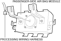
3. Disconnect the connectors.
4. Connect the processing wiring harness to the passenger-side air bag module.
5. Verify that all persons are standing at least 6 m {19 ft} away from the vehicle.
6. Untwist the processing wiring harness.
7. Connect the processing wiring harness to the lead-acid battery and activate the inflator.
Knee air bag module
1. Remove the following parts:
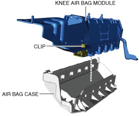
2. Remove the knee air bag module from the air bag case.
ac30zw00003728
|
3. Remove the clips.
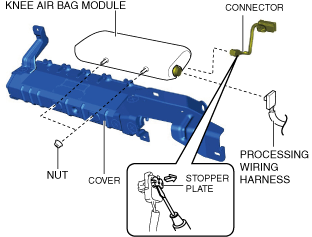
4. Remove the nuts.
ac30zw00004901
|
5. Remove the cover.
6. Pull out the connector stopper plate using a flathead screwdriver.
7. Disconnect the connector.
8. Connect the processing wiring harness to the knee air bag module.
9. Install the cover.
10. Install the nuts.
11. Install the knee air bag module. (See KNEE AIR BAG MODULE REMOVAL/INSTALLATION [TWO-STEP DEPLOYMENT CONTROL SYSTEM].)
12. Verify that all persons are standing at least 6 m {19 ft} away from the vehicle.
13. Untwist the processing wiring harness.
14. Connect the processing wiring harness to the lead-acid battery and activate the inflator.
Side air bag module
1. Remove the front seat. (See FRONT SEAT REMOVAL/INSTALLATION [(E)].)
2. Remove the front seat back trim and seat back pad. (See FRONT SEAT BACK TRIM REMOVAL/INSTALLATION [(E)].)
3. Remove the side air bag module. (See SIDE AIR BAG MODULE REMOVAL/INSTALLATION [TWO-STEP DEPLOYMENT CONTROL SYSTEM].)
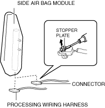
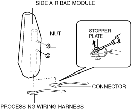
4. Pull out the connector stopper plate using a flathead screwdriver.
am3zzw00037127
|
5. Disconnect the connector.
6. Connect the processing wiring harness to the side air bag module.
7. Install the side air bag module. (See SIDE AIR BAG MODULE REMOVAL/INSTALLATION [TWO-STEP DEPLOYMENT CONTROL SYSTEM].)
8. Install the front seat. (See FRONT SEAT REMOVAL/INSTALLATION [(E)].)
9. Verify that all persons are standing at least 6 m {19 ft} away from the vehicle.
10. Untwist the processing wiring harness.
11. Connect the processing wiring harness to the lead-acid battery and activate the inflator.
Curtain air bag module
1. Remove the following parts:
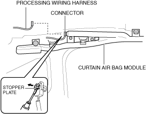
2. Peel back the headliner.
3. Pull out the connector stopper plate using a flathead screwdriver.
a30zzw00002930
|
4. Disconnect the connector.
5. Connect the processing wiring harness to the curtain air bag module.
6. Verify that all persons are standing at least 6 m {19 ft} away from the vehicle.
7. Untwist the processing wiring harness.
8. Connect the processing wiring harness to the lead-acid battery and activate the inflator.
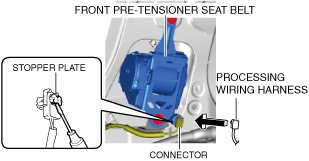
Front pre-tensioner seat belt
1. Remove the following parts:
2. Using a flathead screwdriver, pry out the connector stopper plate.
am3zzw00037128
|
3. Disconnect the connector.
4. Connect the processing wiring harness to the front pre-tensioner seat belt.
5. Verify that all persons are standing at least 6 m {19 ft} away from the vehicle.
6. Untwist the processing wiring harness.
7. Connect the processing wiring harness to the lead-acid battery and activate the inflator.
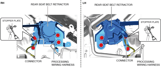
Rear pre-tensioner seat belt
1. Remove the following parts:
2. Using a flathead screwdriver, pry out the connector stopper plate.
ac30zw00004948
|
3. Disconnect the connector.
4. Connect the processing wiring harness to the rear pre-tensioner seat belt.
5. Verify that all persons are standing at least 6 m {19 ft} away from the vehicle.
6. Untwist the processing wiring harness.
7. Connect the processing wiring harness to the lead-acid battery and activate the inflator.
Activation (Deployment) Outside The Vehicle
Driver-side air bag module
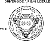
1. Remove the driver-side air bag module. (See DRIVER-SIDE AIR BAG MODULE REMOVAL [TWO-STEP DEPLOYMENT CONTROL SYSTEM].)
2. Wrap the automotive wiring harness (cross section 1.25 mm2{0.002 in2} or more) three times in the position shown in the figure on the driver-side air bag module.
am3zzw00028322
|
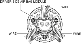
3. Wrap the automotive wiring harness (cross section 1.25 mm2{0.002 in2} or more) four times in the position shown in the figure on the driver-side air bag module.
am3zzw00028323
|
4. Connect the processing wiring harness to the driver-side air bag module.
a30zzw00002933
|
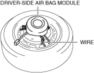
5. With the pad side of the driver-side air bag module facing up, place it in the center of the wheel, and wrap the automotive wiring harness (cross section 1.25 mm2{0.002 in2} or more) four times to secure it.
a30zzw00002934
|
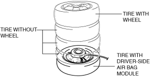
6. Stack three tires without wheels on top of the tire with the driver-side air bag module, and stack another tire with a wheel on the very top.
a30zzw00002935
|
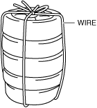
7. Secure the tire with the automotive wiring harness (cross section 1.25 mm2{0.002 in2} or more).
am3uuw00014010
|
8. Verify that all persons are standing at least 6 m {19 ft} away from the tires.
a30zzw00002936
|
9. Untwist the processing wiring harness.
10. Connect the processing wiring harness to the lead-acid battery and activate the inflator.
a30zzw00002937
|
11. Discard the air bag module. (See AIR BAG MODULE AND PRE-TENSIONER SEAT BELT DISPOSAL PROCEDURES [TWO-STEP DEPLOYMENT CONTROL SYSTEM].)
Passenger-side air bag module
1. Remove the following parts:
2. Remove the passenger-side air bag module. (See PASSENGER-SIDE AIR BAG MODULE REMOVAL/INSTALLATION [TWO-STEP DEPLOYMENT CONTROL SYSTEM].)
3. Connect the processing wiring harness to the passenger-side air bag module.
a30zzw00002938
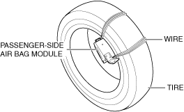
|
4. With the pad surface of the passenger-side air bag module facing the center of the tire, wrap the automotive wiring harness (cross section of 1.25 mm2{0.002 in2} or more) four times to secure it.
a30zzw00002939
|
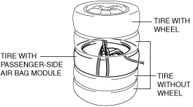
5. Place two tires without wheels on top of each other, place a tire with the passenger-side air bag module fixed, place another tire without a wheel on top of it, and place another tire with a wheel on top.
a30zzw00002940
|
6. Secure the tire with the automotive wiring harness (cross section 1.25 mm2{0.002 in2} or more).
am3uuw00014010
|
7. Verify that all persons are standing at least 6 m {19 ft} away from the tires.
a30zzw00002936
|
8. Untwist the processing wiring harness.
9. Connect the processing wiring harness to the lead-acid battery and activate the inflator.
a30zzw00002937
|
10. Discard the air bag module. (See AIR BAG MODULE AND PRE-TENSIONER SEAT BELT DEPLOYMENT PROCEDURES [TWO-STEP DEPLOYMENT CONTROL SYSTEM].)
Knee air bag module
1. Remove the following parts:
2. Remove the knee air bag module from the air bag case.
ac30zw00003728
|
3. Remove the clip.
4. Remove the nuts.
ac30zw00004901
|
5. Remove the cover.
6. Pull out the connector stopper plate using a flathead screwdriver.
7. Disconnect the connector.
8. Connect the processing wiring harness to the knee air bag module.
9. Install the cover.
10. Install the nuts.
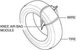
11. With the pad surface of the knee air bag module facing the center of the tire, wrap the automotive wiring harness (cross section 1.25 mm2{0.002 in2} or more) four times to secure it.
am3zzw00028326
|
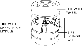
12. Place two tires without wheels on top of each other, place a tire with the knee air bag module fixed, place another tire without a wheel on top of it, and place another tire with a wheel on top.
am3zzw00028327
|
13. Secure the tire with the automotive wiring harness (cross section 1.25 mm2{0.002 in2} or more).
am3uuw00014010
|
14. Verify that all persons are standing at least 6 m {19 ft} away from the tires.
a30zzw00002936
|
15. Untwist the processing wiring harness.
16. Connect the processing wiring harness to the lead-acid battery and activate the inflator.
a30zzw00002937
|
17. Discard the air bag module. (See AIR BAG MODULE AND PRE-TENSIONER SEAT BELT DISPOSAL PROCEDURES [TWO-STEP DEPLOYMENT CONTROL SYSTEM].)
Side air bag module
1. Perform the following procedure. (without Mazda M Hybrid)
2. Perform the following procedure. (with Mazda M Hybrid, with seat warmer system)
3. Remove the following parts:
4. Install the nuts.
am3zzw00037130
|
5. Pull out the connector stopper plate using a flathead screwdriver.
6. Disconnect the connector.
7. Connect the processing wiring harness to the side air bag module.
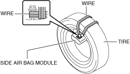
8. With the pad surface of side air bag module facing the center of the tire, wrap the automotive wiring harness (cross section 1.25 mm2{0.002 in2} or more) four times to secure it.
am3zzw00037131
|
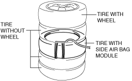
9. Place two tires without wheels on top of each other, place a tire with the side air bag module fixed, place another tire without a wheel on top of it, and place another tire with a wheel on top.
am3zzw00037132
|
10. Secure the tire with the automotive wiring harness (cross section 1.25 mm2{0.002 in2} or more).
am3uuw00014010
|
11. Verify that all persons are standing at least 6 m {19 ft} away from the tires.
a30zzw00002936
|
12. Untwist the processing wiring harness.
13. Connect the processing wiring harness to the lead-acid battery and activate the inflator.
a30zzw00002937
|
14. Discard the air bag module. (See AIR BAG MODULE AND PRE-TENSIONER SEAT BELT DISPOSAL PROCEDURES [TWO-STEP DEPLOYMENT CONTROL SYSTEM].)
Curtain air bag module
1. Remove the following parts:
2. Remove the curtain air bag module. (See CURTAIN AIR BAG MODULE REMOVAL/INSTALLATION [TWO-STEP DEPLOYMENT CONTROL SYSTEM].)
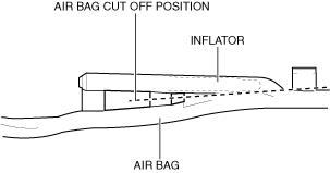
3. Cut off the air bag part of the curtain air bag module at the position shown in the figure.
a30zzw00002949
|
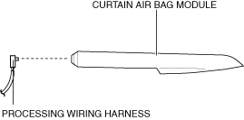
4. Connect the processing wiring harness to the curtain air bag module.
a30zzw00002950
|
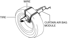
5. Place the curtain air bag on the inside of the tire and wrap the automotive wiring harness (cross section 1.25 mm2{0.002 in2} or more) four times to secure it.
a30zzw00002951
|
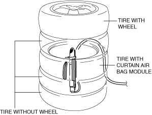
6. Place two tires without wheels on top of each other, place a tire with the curtain air bag module fixed, place another tire without a wheel on top of it, and place another tire with a wheel on top.
a30zzw00002952
|
7. Secure the tire with the automotive wiring harness (cross section 1.25 mm2{0.002 in2} or more).
am3uuw00014010
|
8. Verify that all persons are standing at least 6 m {19 ft} away from the tires.
a30zzw00002936
|
9. Untwist the processing wiring harness.
10. Connect the processing wiring harness to the lead-acid battery and activate the inflator.
a30zzw00002937
|
11. Discard the air bag module. (See AIR BAG MODULE AND PRE-TENSIONER SEAT BELT DISPOSAL PROCEDURES [TWO-STEP DEPLOYMENT CONTROL SYSTEM].)
Front pre-tensioner seat belt
1. Remove the following parts:
2. Remove the front seat belt. (See FRONT SEAT BELT REMOVAL/INSTALLATION.)
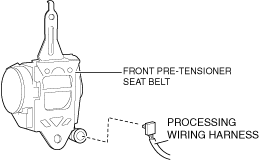
3. Connect the processing wiring harness to the front pre-tensioner seat belt.
am3zzw00037133
|
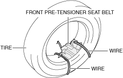
4. With the pre-tensioner mechanism inside the tire, wrap the automotive wiring harness (cross section 1.25 mm2{0.002 in2} or more) four times to secure it.
a30zzw00002954
|
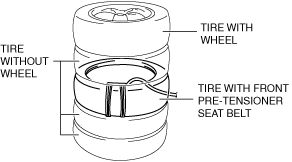
5. Place two tires without wheels on top of each other, place a tire with the front pre-tensioner seat belt fixed, place another tire without a wheel on top of it, and place another tire with a wheel on top.
a30zzw00002955
|
6. Secure the tire with the automotive wiring harness (cross section 1.25 mm2{0.002 in2} or more).
am3uuw00014010
|
7. Verify that all persons are standing at least 6 m {19 ft} away from the tires.
a30zzw00002936
|
8. Untwist the processing wiring harness.
9. Connect the processing wiring harness to the lead-acid battery and activate the inflator.
a30zzw00002937
|
10. Discard the front pre-tensioner seat belt. (See AIR BAG MODULE AND PRE-TENSIONER SEAT BELT DISPOSAL PROCEDURES [TWO-STEP DEPLOYMENT CONTROL SYSTEM].)
Rear pre-tensioner seat belt
1. Remove the following parts:
2. Pull away the trunk side trim enough to secure a space for a hand to be inserted between body panel and trunk side trim. (See TRUNK SIDE TRIM REMOVAL/INSTALLATION [(E)].)
3. Remove the parking assist unit (ultrasonic) (rear seat belt (RH) (with parking assist unit (ultrasonic)). (See PARKING ASSIST UNIT (ULTRASONIC) REMOVAL/INSTALLATION.)
4. Remove the rear seat belt. (See REAR SEAT BELT REMOVAL/INSTALLATION [(E)].)
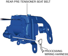
5. Connect the processing wiring harness to the rear pre-tensioner seat belt.
ac30zw00004949
|
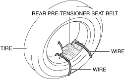
6. With the pre-tensioner mechanism inside the tire, wrap the automotive wiring harness (cross section 1.25 mm2{0.002 in2} or more) four times to secure it.
am6zzw00016147
|
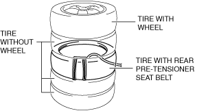
7. Place two tires without wheels on top of each other, place a tire with the rear pre-tensioner seat belt fixed, place another tire without a wheel on top of it, and place another tire with a wheel on top.
am6zzw00016144
|
8. Secure the tires with the automotive wiring harness (cross section 1.25 mm2{0.002 in2} or more).
am3uuw00014010
|
9. Verify that all persons are standing at least 6 m {19 ft} away from the tires.
a30zzw00002936
|
10. Untwist the processing wiring harness.
11. Connect the processing wiring harness to the lead-acid battery and activate the inflator.
a30zzw00002937
|
12. Discard the air bag module. (See AIR BAG MODULE AND PRE-TENSIONER SEAT BELT DISPOSAL PROCEDURES [TWO-STEP DEPLOYMENT CONTROL SYSTEM].)